6
Installing Thermoswitch
Bird 8860 series loads can be equipped with an optional interlock thermoswitch, P/N 8890-008. It is normally closed,
opening at 236 °C (457 °F), with a rating of 10A @ 120Vac and 5A @ 230Vac.
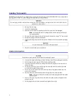
1.
Remove the vent plug.
2.
Install the shipping plug.
3.
Stand the unit on its front, supporting it so that the connector is not damaged.
Note:
In this position there is no danger of the coolant pouring out through
the socket plug hole.
4.
Remove the socket plug just above the connector assembly, using a
9
⁄
16
" hex wrench.
5.
Replace the plug with the thermoswitch.
6.
Apply pipe sealing compound to the external threads of the thermoswitch sparingly,
ONLY.
1.
Check for coolant leaks upon completion.
Interlock Connection
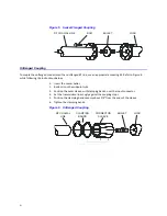
1.
Unscrew the large knurled ring-nut (A) at the lower end of the coupling jack assembly.
2.
Pull the large knurled ring-nut off the thermoswitch jack (B).
3.
Unscrew the small knurled cover fitting from the base plug (D) of the connector to
release the base.
4.
Thread the control switch wires through the clamp (E) with the washers (F) inside
and with its threaded fitting in place.
5.
Service the control switch wire with short tips and put spaghetti sleeves over the
wire ends if necessary.
6.
Securely solder the control switch leads to the lugs (G) of the connector base.
Note:
The ring-nut (A) must be in place over the base plug (D) with the knurled
end facing out.
7.
Screw on the cover ring, then fasten the cable clamp (E) in place and tighten both
yoke screws (H).
2.
Put the plug back on the thermoswitch and tighten the nut (A).
WARNING
The vent plug must be used at all times when the unit is operating or cooling. Failure to do so could result in an
explosion or severe burns.
CAUTION
Do not contaminate the coolant with pipe sealant.
CAUTION
If installed, connect optional interlock before applying RF power.


