background image

VTS1053

PHOTOELECTRIC EYE

OPERATING INSTRUCTIONS

Starting Operation

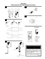
1. Open the cover and guard of the sensor; make sure that no dirt enters the device.

2. Select switching function:

L.ON: Light-switching if light received, output (Q) switches.

D.ON; Dark-switching if light interrupted, output (Q) switches.

WT 260-R and -S only: Light-switching: Relay 1x u, separated galvanically.

3. With following connectors only:

Connect and secure cable receptacle tension-free

Only in versions with terminal clamp area:

Loosen ½" PF screwed connection, remove sealing plugs.

Cable outlets downward or to the back. Pass the dead power supply line through and connect the sensor
according to connection diagram.

4. Close the protective cap.

Mount the sensor using the mounting holes and align it roughly.

Connect the operating voltage to the sensor (see Type imprint).

Check scanning distance, and compare with characteristic in diagram (x = scanning distance, y = operating
reserve).

Reflectance: 6% = black, 18% = gray, 90% = white (based on standard white to DIN 5033).

Aligning light reception:

Position the object. Align the WT 260 with the object. Turn the knob >SENS, <to max. When the light
reception is optimal, the switching output switches into the state set in.

If no or too little light is received, realign the photoelectric proximity switch with the object and check the
application conditions.

5. Setting the sensitivity (SENS):

Remove the object. The switching output switches (Pos. A = Max).

When there is interference from the background:

Turn the knob (turning range 270º) in the direction of min. (e.g. position A). Set the rotary knob to min.
Position the object. Turn the knob in the direction of max. until the switching output switches (e.g.
position B).

If position B < position A:

Select the middle setting (e.g. position C). Check overall operation. If operation is OK, setting is
completed. IF operation is not OK, check the application conditions and realign.

If position A < position B:

Background influence is excessive. Check the application conditions and realign. Check sealing faces,
seals, and screwed joints, then replace and screw down cover.

Maintenance

SICK photoelectric switches do not require any maintenance.

We recommend that you clean the optical interfaces and check the screw connections and plug-in
connections at regular intervals.

12

Summary of Contents for VTS-100

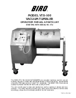
Page 1: ...rbs and spices All marinades should be FDA approved and meet F S I standards The BIRO VTS 100 produces equally impressive results with beef pork poultry and fish The unit is both easy to clean and maintain as well as sanitary in design and con struction The entire machine is built to give many years of trouble free service while providing a unique line of marinated products for your customers ITEM...

Page 2: ...TENANCE FOR GEAR REDUCER 10 11 PHOTOELECTRIC EYE OPERATING INSTRUCTIONS 12 13 CONTROL PANEL COMPONENTS 14 CONTROL PANEL REAR VIEW 15 DRUM ASSEMBLY 16 FRAME ASSEMBLY AND COMPONENTS 17 VACUUM HOSES AND FITTINGS 18 19 COMPONENT COVER AND REAR DOOR 20 WIRING DIAGRAMS 21 22 RECOMMENDED SPARE PARTS 23 OPERATOR S NOTES 24 OPERATOR S SIGNATURE PAGE 25 LIMITED WARRANTY 26 ...

Page 3: ...ge should operate this equipment If you are uncer tain about a particular task ask your supervisor This Manual contains a number of safe practices in the SAFETY TIP section Additional warn ings are placed throughout the Manual Warnings related to your personal safety are indicated by Warnings related to possible damage to equipment are indicated by BIRO also has provided warning labels on the equi...

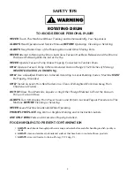
Page 4: ...lding Codes Machine MUST Be Properly Grounded ONLY Install on Level Non Skid Surface in a Clean Well Lighted Work Area Away From Children and Visitors DO NOT Allow Food Particles Liquids or Any Other Foreign Material to Enter the Vacuum Pump or Vacuum Hose ALWAYS Turn Off Unplug From Power Source and Perform Lockout Tagout Procedure to This Machine BEFORE Cleaning or Servicing NEVER Leave Machine ...

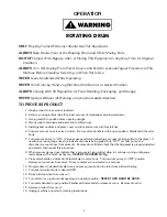
Page 5: ...ve on drum Be sure valve handle is in the open position Parallel with the valve body 7 Turn vacuum pump to ON Vacuum gauge will start indicating a vacuum is being pulled in the drum If needle in vacuum gauge does not indicate vacuum is being pulled turn OFF vacuum pump and disconnect vacuum hose from drum lid Remove drum lid and check that the lid gasket is properly installed and seated then repea...

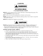
Page 6: ...achine for Any Length of Time CLEANING THE BIRO VACUUM TUMBLER 1 Turn OFF unplug machine from power source and perform lockout tagout procedures 2 The drum drum lid and gasket can be removed and washed in utensil sink Be sure to flush the vacuum valve on drum with warm soapy water and rinse with clean water thoroughly The drum drum lid and gasket should be sanitized with an appropriate sanitizer a...

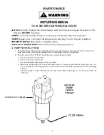
Page 7: ...rained before the separated moisture and oil reaches the bottom of the lower black baffle Drain by unscrewing the black drain plug in bottom of sight bowl 2 The filter element No VTS529 1 should be removed and cleaned monthly a Unscrew the black locking collar b Remove bowl and locking collar c Unscrew the black baffle at the bottom of the filter d Clean bowl and filter element Reinstall the filte...

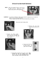
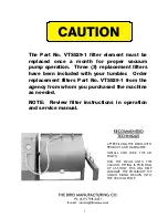
Page 8: ...ion Three 3 replacement filters have been included with your machine 1 Unscrew the bowl locking collar 2 Remove the clear bowl and locking collar and set aside 3 Unscrew the filter holder Lower the filter carefully from the mounting stud Note the order of parts 4 Separate the filter from the filter holders Re place with a new filter 5 Reassemble the filter in the reverse order Take special care th...

Page 9: ...ent filters Part No VTS529 1 from the agency from whom you purchased the machine as needed NOTE Review filter instructions in operation and service manual 7 AFTER FILLING THE DRUM WITH PRODUCT AND MARINADES INSTALL AND LOCK THE LID DOWN JOG THE DRUM UNTIL THE VACUUM FITTING IS POINTING UP AS SHOW THIS WILL HELP MINIMIZE THE POSSIBILITY OF LIQUID BEING DRAWN INTO THE VACUUM PUMP ...

Page 10: ... pipe nipples at least 4 long with 3 8 NPT on one end 1 Remove the filter elements from the front of the muffler box and screw the nipples in through the same holes 2 With the pump running allow about 2 tbsp of flushing solvent to be ingested into the vacuum side of the unit CAUTION WEAR EYE PROTECTION AND FLUSH IN A WELL VENTILATED AREA Repeat the flushing procedure If it does not remedy the situ...

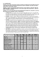
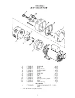
Page 11: ... req d 5 VTS AK522 Gasket 1 req d 6 VTS AK520 Muffler box 1 req d 7 VTS AK473 O ring 2 req d 8 VTS AK524 Felt 2 req d 9 VTS AK510 End cap 2 req d 10 VTS AK526 End cap assembly 8 9 2 req d 11 VTS AK512 Rotor 1 req d 12 VTS AD126 Tolerance ring 1 req d NOT SHOWN VTS1034 1K Service kit consists of 2 5 7 8 9 K479 11 12 Should not be replaced in field ...

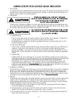
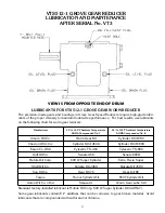
Page 12: ...te over a wider temperature range These oils are appropriate for any application but are especially useful when units are subjected to low start up temperatures or high operating temperatures Use of synthetics can cause problems if they are not compatible with the seals or the conventional lubricants they replace For continuous duty at normal ambient temperatures 10 F to 105 F we recommend the use...

Page 13: ...Temperature AGMA Compounded No 8 Amoco Oil Co Worm Gear Oil Cylinder Oil 680 Chevron USA Inc Cylinder Oil 460X Cylinder Oil 680X Exxon Co USA Cylesstic TK 460 Cylesstic TK 680 Gulf Oil Co Senate 460 Senate 680D Mobile Oil Corp 600 W Super Cylinder Extra Hecla Super Shell Oil Co Valvata Oil J460 Valvata Oil J680 Sun Oil Co Gear Oil 7C Gear Oil 8C Texaco Honor Cylinder Oil 650T Cylinder Oil Union Oi...

Page 14: ... Position the object Align the WT 260 with the object Turn the knob SENS to max When the light reception is optimal the switching output switches into the state set in If no or too little light is received realign the photoelectric proximity switch with the object and check the application conditions 5 Setting the sensitivity SENS Remove the object The switching output switches Pos A Max When ther...

Page 15: ...e Operating Instructions 13 This tumbler contains a photo sensor light beam as a safety barrier If a person or object blocks the beam the machine will STOP Clear the photo sensor beam press the start button to resume operation ...

Page 16: ...HZ VTS7211 Transformer 220V Estop VTS7213 Bulb 120V 60HZ Item No Description HHS004S Hex head screw 8 32 x 3 8 SS HHS035S Hex head screw 1 4 20 x 5 8 S S HHS013S ST Hex head screw 10 16 x 3 4 self tap LW10S Lock washer 1 4 S S PC154 Jog on switch w buttons Black Green RHS03S Round head screw 6 32 x 3 4 S S RHS021S Round head screw 6 32 x 1 2 S S T3187 5 Circuit breaker 15 AMP VT450S Timer socket V...

Page 17: ...15 CONTROL PANEL REAR VIEW ...

Page 18: ...eldment VTS1036 2 Drum weldment VTS1037 2 Drum gasket VTS1081 1 Drum cover handle VTS1083 7 Mounting block VTS1083 8 Lid latch VTS1083 9 Latch keeper plate VTS361 Drain plug VTS363 1 Drain cap delrin 15 8 12 thread VTS7116 90º elbow 3 8 MPT 3 8 FPT SS VTS7152 Ball valve SS VTS7194 Quick coupling nipple SS ...

Page 19: ...036 2 Drum weldment VTS1037 2 Drum gasket VTS1048 Rear door Item No Description VTS1053 Photoelectric eye VTS1075 Sight window 2 dia VTS1083 8 Lid latch VTS1092 Pulley aluminum 9 bore VTS1122 Key 3 16 3 16 13 8 SS VTS324B Roller chain coupling hub 1 bore VTS324C Chain assembly VTS324F Roller chain coupling hub 11 8 bore VTS325 1A Pillow block bearing shim VTS325 2 Pillow block Delrin VTS325SHM Pil...

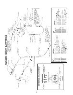
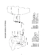
Page 20: ...ch 3 8 pipe brass VTS587 Nipple 2 inch 3 8 pipe brass VTS591 Nipple 1 3 8 3 8 pipe brass VTS592 Elbo 90º 3 8 pipe brass Item No Description VTS7002 Vacuum gauge VTS7117 Tee barb plastic 3 8 3 8 3 8 VTS7118 Straight barb brass FPT 3 8 VTS7132 Washer aluminum 1 3 16 O D 11 16 I D VTS7155 9 Vacuum hose 9 inch VTS7155 10 Vacuum hose 10 inch VTS7155 15 Vacuum hose 15 inch Nylobrade VTS7155 19 Vacuum ho...

Page 21: ...m 1 3 16 O D 11 16 I D 1 16 TK VTS7152 Ball valve SS VTS7155 1 Hose w 3 8 crimped fitting 38 long Item No Description VTS7155 9 Vacuum hose 9 nylobrade VTS7158 Hose barb 3 8 MPT 3 8 1 3 8 barb lg VTS7159 90 degree elbow 3 8 FPT 3 8 FPT SS VTS7160 90º street MPT FPT brass VTS7172 Vacuum gauge label VTS7193 B Quick coupler BST 3 VTS7194 B Nipple quick coupler BST N3M VTS7214 Hose barb 3 8 MPT 1 barb...

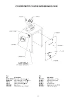
Page 22: ...crew 20 5 8 S S PC159 Strain relief fitting dia PC161 Strain relief fitting 7 8 dia VTS1048 Rear door VTS1053 Photoelectric eye w bracket Item No Description VTS1075 Sight window 2 dia VT460S Model and S N plate VT464S Filter label VT481S Locking knob VTS580 Component cover NSS VTS7197 Filter access panel ...

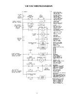
Page 23: ...120 VAC WIRING DIAGRAM 21 ...

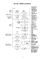
Page 24: ...220 VAC WIRING DIAGRAM 22 ...

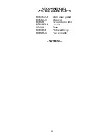
Page 25: ...RECOMMENDED VTS 100 SPARE PARTS NOTES 23 VTS1037 2 Drum cover gasket VTS363 1 Drain cap VTS529 Vacuum pump filter VTS1083 8 Latches VT492S Timer VTS1053 Photoelectric eye VTS529 1 Filter elements ...

Page 26: ... NOTES 24 ...
Page 27: ... ENTIRE MANUAL BEFORE SIGNING BELOW MY SIGNATURE ATTESTS THAT I HAVE COMPLETELY READ AND UNDERSTAND THIS MANUAL I REALIZE THAT THIS MACHINE IF OPERATED CARELESSLY CAN CAUSE SERIOUS INJURY TO MYSELF AND OTHERS NAME PRINT SIGNATURE DATE 25 SUPERVISOR S INITIALS ...

Page 28: ... part covered by this limited warranty or for any damages resulting from misuse abuse lack of proper or recommended service Failure to follow drum loading procedure will result in liquid collecting inside the vacuum pump which voids this warranty EXCLUSION OF WARRANTIES AND LIMITATION OF REMEDIES BIRO gives no warranties other than those expressly stated in this limited warranty THE IMPLIED WARRAN...

Reviews: