background image

Bischoff & Bischoff GmbH | 12.05.2016

EN

21

20

PYRO LIGHT OPTIMA

 | Lightweight wheelchair

Lightweight wheelchair | 

PYRO LIGHT OPTIMA

4.7. Brakes

4.7.1 Setting the parking brake

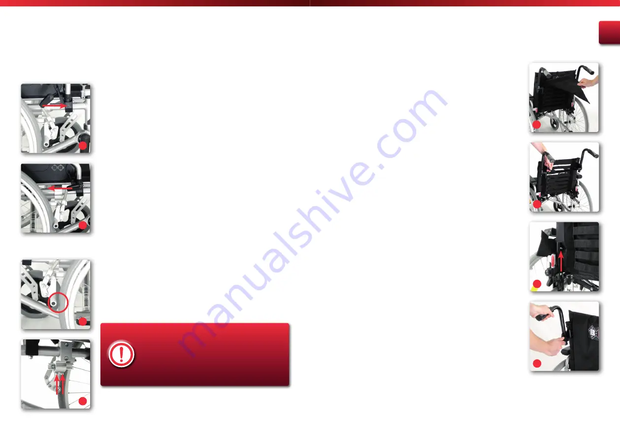
To lock the brake, simply push the brake lever forwards until it locks 
(fig. 26). To release the locking brake, simply pull the brake lever 
backwards (fig. 27).

4.7.2 Adjusting the brakes

If you notice that the available braking effect is no longer sufficient or 
is uneven, proceed as follows:
 

• 

Check the tyre profile depth. At the same time, check for even wear 
of the tyres. If the profile depth in the middle of the tread is less 
than 1mm, the tyre must be changed. If you have the necessary 
technical experience you can change the tyre yourself, if you do not 
feel confident to do this yourself, your specialist retailer will be able 
to help you.

• 

Now check the adjustment of the brake. This must be set so that 
the gap between the surface of the wheel and the braking bolt 
is 15 mm with the brake off (fig. 28). The braking bolt must be 
aligned horizontally, that is parallel to the ground surface.

• 

After unscrewing the two rounded head bolts with 5 mm Allen 
head on the brake mounting (fig. 29), you can position the brake 
correctly.

The brakes only operate on one driving wheel each!
Ensure that both drive wheels have the same tyre 
pressure with pneumatic tyres to achieve good 
directional stability! 
After completion of the setting process, retighten
the loosened bolts and test the brakes!

26

28

29

27

31

33

32

4.8. Backrest

The tension of the backrest can be adjusted to enable you to sit 
comfortably in the wheelchair. Additionally the height of the backrest 
can also be adjusted.

4.8.1 Backrest cover

The tauter you adjust the backrest cover, the harder it feels. First remove 
the backrest padding that is attached by Velcro tape (fig. 30).

Then you can adjust each of the belts so that they are firmer or less firm 
(fig. 31). To lessen the tension on particular parts of your back, loosen 
the belt there a little. Now you have to re-secure the back padding by 
means of the Velcro tape.

4.8.2 Backrest height

To adjust the backrest height it is recommended that the side parts and 
the back padding are removed first. You can then loosen the screws on 
both sides (fig. 32) and adjust the frame to the desired height. Then 
put the screws back into the holes provided and screw them firmly in.

4.9. Push handles

The height of the push handles can be adjusted to make it comfortable 
for an accompanying person to push you. Loosen the lever screw  
(fig. 33) on the push handles and adjust them to the required height. 
Then firmly tighten the lever screws again to lock the push handles.

30

Summary of Contents for Pyro light Optima

Page 1: ...Enjoy mobility Bedienungsanleitung Enjoy mobility Instruction Manual Pyro Light Optima Pyro Light Optima XL...

Page 2: ...intenance tips for retailers 32 12 Use by others 32 13 Storage shipping 32 14 Disposal 33 15 Warranty 33 Index 1 Preliminary remark 04 1 1 Signs and symbols 04 2 Important safety instructions 05 2 1 G...

Page 3: ...ipment such as ramps lifts or step climbing aids are available these should be used When driving on an incline or slope it is necessary to be aware that a risk of tipping exists even at low angles dep...

Page 4: ...M TSI Annex M in terms of size and manoeuvring range When transferring between wheelchair and bed always ensure that both parking brakes are applied the side part on the side for getting in out is swu...

Page 5: ...s repairs or maintenance works are made please make sure only authorised persons perform these works in accordance to the instructions of B B 2 9 Service life If used as intended and the safety care a...

Page 6: ...Foot rests Foot plate Steering wheel 1a Wider seat width Double crossbrace Foot plate extendible 1b Model Pyro Light Optima Model Pyro Light Optima XL Bischoff Bischoff GmbH Becker G ring Stra e 13 D...

Page 7: ...by pulling the backrest to you until the weight is taken off the opposite driving wheel At the same time pull the seat cover upwards until the chair is completely folded fig 5 5 3 4 To prevent injurie...

Page 8: ...ed position by rotating the toothed ring Retighten the Allen bolt 10 80 mm 4 2 7 Width of the foot plates You can adjust the width of the foot plates Loosen the fastening screw on the foot plate then...

Page 9: ...i tip wheels or a wheelbase extension are necessary Check the settings first with a helper Only use settings that you feel safe with 15 16 17 Afterwards remove the Allen bolts at the back on the seat...

Page 10: ...eeply and firmly in the chair To incline the seat towards the back attach the quick release axle in a higher position If you wish to incline the seat towards the front fix the quick release axle in a...

Page 11: ...n one driving wheel each Ensure that both drive wheels have the same tyre pressure with pneumatic tyres to achieve good directional stability After completion of the setting process retighten the loos...

Page 12: ...ter of 8 x 1 1 4 Pyro Light Optima XL 200 x 50 mm are mounted on your Pyro light Optima as standard If they become worn or defective the authorised mobility dealer should be requested to undertake the...

Page 13: ...uired a safety belt is available as an accessory This is mounted on the side frame of the wheelchair with the side part either temporarily removed or swung away fig 41 Take the open end of the belt on...

Page 14: ...nd on the footrest Risk of tipping For obstacles and stairs with more than three steps two accompanying people must help 7 2 Entering and leaving from the front First fold the foot plates up or remove...

Page 15: ...ity forwardly the wheelchair will tip over backwardly According to STVZO 66 1 German Road Traffic Act of 01 01 1981 hand propelled wheelchairs require permanently attached lighting to participate in p...

Page 16: ...erature C 40 Air humidity 80 Tyres Drive wheels 24 x 1 3 8 610 x 35 mm PU Steering wheels 8 x 1 1 4 200 x 50 mm PU Equipment Folding mechanism single cross brace double cross brace Side parts height a...

Page 17: ...for transporting disabled people and the basis for the approval The restraint systems from AMF Bruns provide the ideal points for the provision of restraint force for the purpose of securing the produ...

Page 18: ...dance to the service plan and must be in good condition 11 Maintenance tips for retailers We recommend having the wheelchair inspected by your qualified mobility dealer at least once a year If faults...

Page 19: ...se contact your dealer 15 Warranty The warranty covers all defects of the wheelchair that are demonstrably due to material or manufacturing defects Any claim must be accompanied by the completely fill...

Page 20: ...number to be filled in by authorized dealer Dealer Date and stamp Please note our general business terms and conditions The serial number is located on the side frame Notes Tip In spite of careful re...

Page 21: ...Bischoff Bischoff GmbH Becker G ring Stra e 13 D 76307 Karlsbad www bischoff bischoff com...

Reviews: