50
Installation Manual: BIPV Modules
49
Installation Manual: BIPV Modules
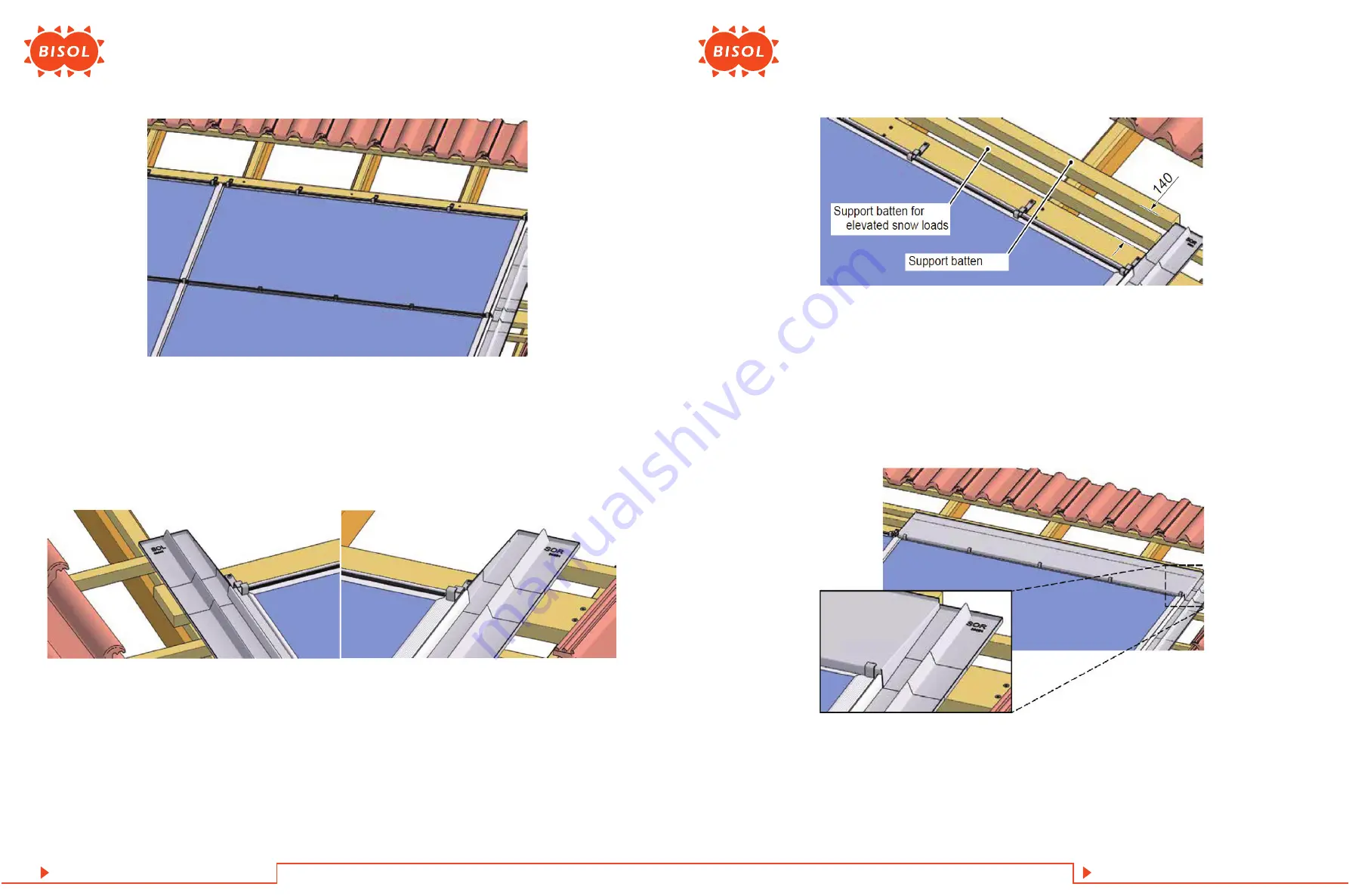
Figure 55: Insert flashing top right
Figure 52: Top row mounting clamp positions and spacing (maximum number of clamps in
this example)
Figure 53: Array top left and right
1. Push the flashing side top right into the flashing profile underneath it.
2. Push the flashing side top left into the flashing profile underneath it.
3. Ensure that the side flashings on the top left-hand side and the top right-hand side are sufficiently supported at the top
end, e. g. by tiling battens.
Figure 54: Support battens
5�3�9 Top of the Array
14. Depending on the roof plan: Insert further Mounting Clamps Profile accordingly.
4. Mount a 40 mm thick support batten under the top ends of the flashing tops; distance between the top edge of the top
batten and the bottom edge of the support batten = 140 mm.
For elevated snow loads:
5. Mount another support batten that is approx. 45 mm thick in the middle between the top batten and the support batten
that has just been placed.
6. Push the flashing top right into the mounting clamp underneath it and over the vertical side of the flashing side top right.


