background image

BT-410F and BT-410A Operation manual


P/N:410-ENG-OPM-EUR-R12 

Bistos Co.,Ltd. 

2021,05 

14 

commercial 

or 

hospital 

environment. 

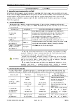
Voltage dips, short 
interruptions and 
voltage variations 
on power supply 
input lines 
IEC 61000-4-11 

0 % UT for 0.5 cycle 

At 0˚, 45˚, 90˚, 135˚, 

180˚, 225˚, 270˚, 315˚ 


0% UT for 1 cycle 

At 0˚, 180˚ 


50 Hz : 

70 % UT for 25 cycles 

At 0˚, 180˚ 


50 Hz : 

0 % UT for 250 cycles 

At 0˚, 180˚ 

0 % UT for 0.5 cycle 

At 0˚, 45˚, 90˚, 135˚, 

180˚, 225˚, 270˚, 315˚ 


0% UT for 1 cycle 

At 0˚, 180˚ 


50 Hz : 

70 % UT for 25 cycles 

At 0˚, 180˚ 


50 Hz : 

0 % UT for 250 cycles 

At 0˚, 180˚ 

Mains power quality should 
be that of a typical 
commercial or hospital 
environment. If the user 
requires continued 
operation during power 
mains interruptions, it is 
recommended that the BT-
410F and BT-410A be 
powered from 
uninterruptable power 
source, battery. 

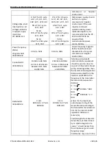
Power frequency 
(50Hz) 

magnetic field 
IEC61000-4-8 

30 A/m, 50Hz 

30 A/m, 50Hz 

Power frequency magnetic 
fields should be at levels 
characteristic of a typical 
commercial or hospital 
environment. 

Conducted RF   

IEC61000-4-6 

3 Vrms 

150 kHz to 80 MHz 


6 Vrms in ISM bands 

between 0.15 MHz 

and 80 MHz 

3 Vrms 

150 kHz to 80 MHz 


6 Vrms in ISM bands 

between 0.15 MHz 

and 80 MHz 

Portable and mobile RF 
communications equipment 
should be used no closer to 
any part of the electric breast 
pump, including cables, than 
the recommended separation 
distance calculated from the 
equation applicable to the 
frequency of the transmitter. 
Recommended separation 
distance: 
d = 1.2

P


d = 1.2

P

  80 MHz ~ 800 

MHz 
d = 2.3

P

  800 MHz ~ 2.7 

MHz 


where P is the maximum 
output power rating of the 
transmitter (W) according to 
the transmitter manufacturer 
and d is the recommended 
separation distance in 
meters(m). 


Field strengths from fixed RF 
transmitters, as determined 
by an electromagnetic site 
survey 

a

, should be less than 

the compliance level in each 
frequency range 

b


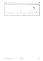
Interference may occur in the 

Radiated RF 

IEC61000-4-3 

3 V/m 

80 MHz to 2.7 GHz 

80% AM 

3 V/m 

80 MHz to 2.7 GHz 

80% AM 

Summary of Contents for BT-410A

Page 1: ...BT 410F and BT 410A Head worn light Operation Manual Keep this manual for future reference P N 410 ENG OPM EUR R12...

Page 2: ...e However no responsibility is assumed by Bistos Corporation For its use or any infringements of patents or other rights of third parties that may result from its use No license is granted by implicat...

Page 3: ...7 2 1 Product outlook and description 7 2 2 Loupe optional assembly 8 2 3 Astral lamp optional assemble 9 3 Operation 9 3 1 Adjust the headband 9 3 2 Turn on the power 9 3 3 Focusing the light 9 3 4...

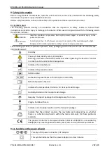
Page 4: ...n product label packaging and this manual in order to stand for the information about Stand by Those symbols identify safety information Warning and caution necessarily well know when operating the de...

Page 5: ...old environment to a warm humid location Do not attempt to service the BT 410F and BT 410A Only qualified service personnel should attempt any needed internal servicing 0 3 Battery warnings WARNING Do...

Page 6: ...rief Device Description Product Features Model Configurations 1 2 Brief device description This Head worn light is used for medical examination by fixing it on the head and illuminating with condensed...

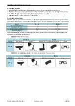
Page 7: ...0A has Fixed Focus lens but BT 410F has Variable focus lens BT 410F and BT 410A system consists of the following function and elements Model BT 410F BT 410A Control of Light Intensity X O Control of L...

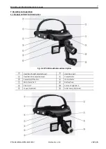
Page 8: ...ration 2 1 Product outlook and description Fig 2 1 BT 410A outlook and description Headband height adjustable part Headband part Headband size adjustable part Protect band Power On Off button LED indi...

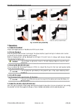
Page 9: ...e shown below Fig 2 3 Loupe Assembly 2 3 Astral lamp optional BT 410A only assembly The astral lamp can be assembled at the bottom of light source Remove the lens cap from the light source and connect...

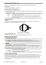
Page 10: ...e high charging voltage may cause the device malfunction 3 3 Focusing the light BT 410F only You can adjust the focal length between 25 30 cm Adjust the focus for the best light quality before treatme...

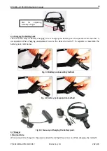
Page 11: ...r is unseparated When charging unseparated be sure the device turned off To separate or assemble the battery pack refer below Fig 3 1 Battery pack assembly method Fig 3 2 Battery pack separation metho...

Page 12: ...s during surgery or other cases 4 Maintenance and cleaning 4 1 Checking the light intensity It is recommended that the intensity of the light be checked before each use and at least every six months W...

Page 13: ...h device or you have further questions please contact Bistos customer center 6 Specifications The BT 410F and BT 410A head worn light is classified as follows in accordance with EN IEC 60601 1 Categor...

Page 14: ...ons flicker emissions IEC61000 3 3 Complies WARNING The BT 410F and BT 410A should not be used adjacent to or stacked with other equipment If adjacent or stacked use is necessary the device should be...

Page 15: ...equency magnetic fields should be at levels characteristic of a typical commercial or hospital environment Conducted RF IEC61000 4 6 3 Vrms 150 kHz to 80 MHz 6 Vrms in ISM bands between 0 15 MHz and 8...

Page 16: ...d with the following symbol IEC 60417 Ref no 5140 Non ionizing electromagnetic radiation Note 1 At 80 MHz and 800 MHz the higher frequency range applies Note 2 These guidelines may not apply in all si...

Page 17: ...t is manufactured and passed through strict quality control and inspection Compensation standard concerning repair replacement refund of the product complies with Framework Act on Consumers noticed by...

Reviews: