Preliminary
Electrical Interfacing
General Purpose Outputs (GPOUT)
Version F.0
BitFlow, Inc.
KBN-7-9
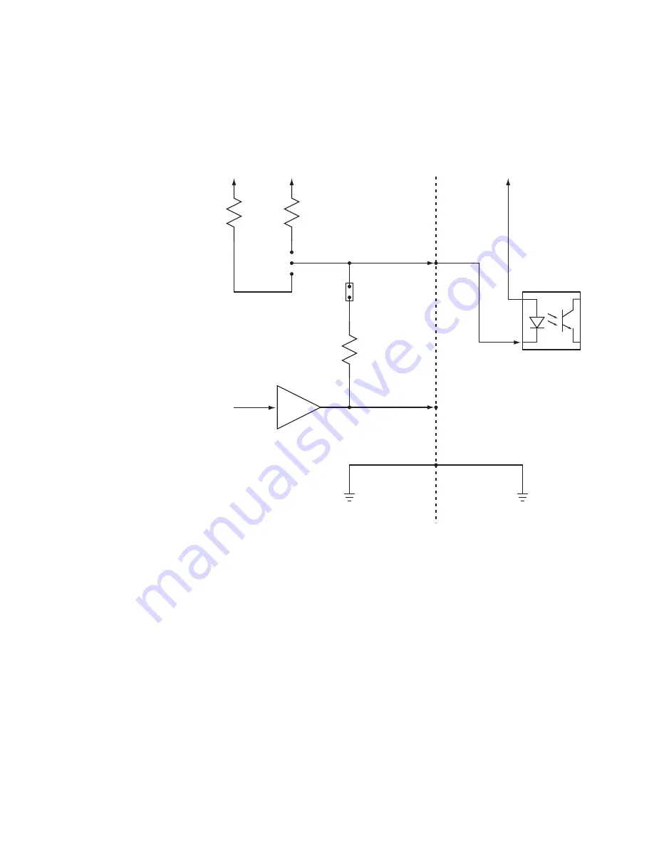
Figure 7-4 shows how the open collector GPOUT5 in the factory configuration can
drive an opto-coupling device. The user must supply the +5V to his LED and the two
systems must have their grounds connected. In this configuration the board and the
user’s system must have a common electrical ground.
Figure 7-4 GPOUT5 Driving Opto-Coupled Circuit (in Default Configuration)
Figure 7-5 shows how the board’s open collector GPOUT5 can drive an user’s opto-
coupled device configured for galvanic isolation between the board and the user. The
power to the user’s LED is supplied by the board’s 5V through a 220 Ohm resistor.
This is achieved by inserting the short in position 1-2 at JP1. The jumper at JP2 is
removed. The open collector driver will sink the current from the LED. There is no gal-
vanic connection between the board and the user’s circuit. Information is passed from
the board to the user as light, transmitted by the LED and received by the photo-tran-
sistor.
GPOUT5
JP2
JP1
+12V
+5V
+5V
GPOUT5_VCC
P3-Pin 32
GPOUT5_OC
P3-Pin 31
GND
P3-Pin 29
7407
1K
220
680
User Circuit
Opto-Coupler
1
2
3
Summary of Contents for KBN-CL4-2.51-SP
Page 20: ...P r e l i m i n a r y The Karbon CL Models The Karbon KBN 1 12 BitFlow Inc Version F 0 ...
Page 62: ...P r e l i m i n a r y DEST_ADD The Karbon KBN 3 8 BitFlow Inc Version F 0 ...
Page 190: ...P r e l i m i n a r y Camera Link Controls CCs The Karbon KBN 7 12 BitFlow Inc Version F 0 ...


