Preliminary
General Description and Architecture
General Description
Version F.0
BitFlow, Inc.
KBN-1-9
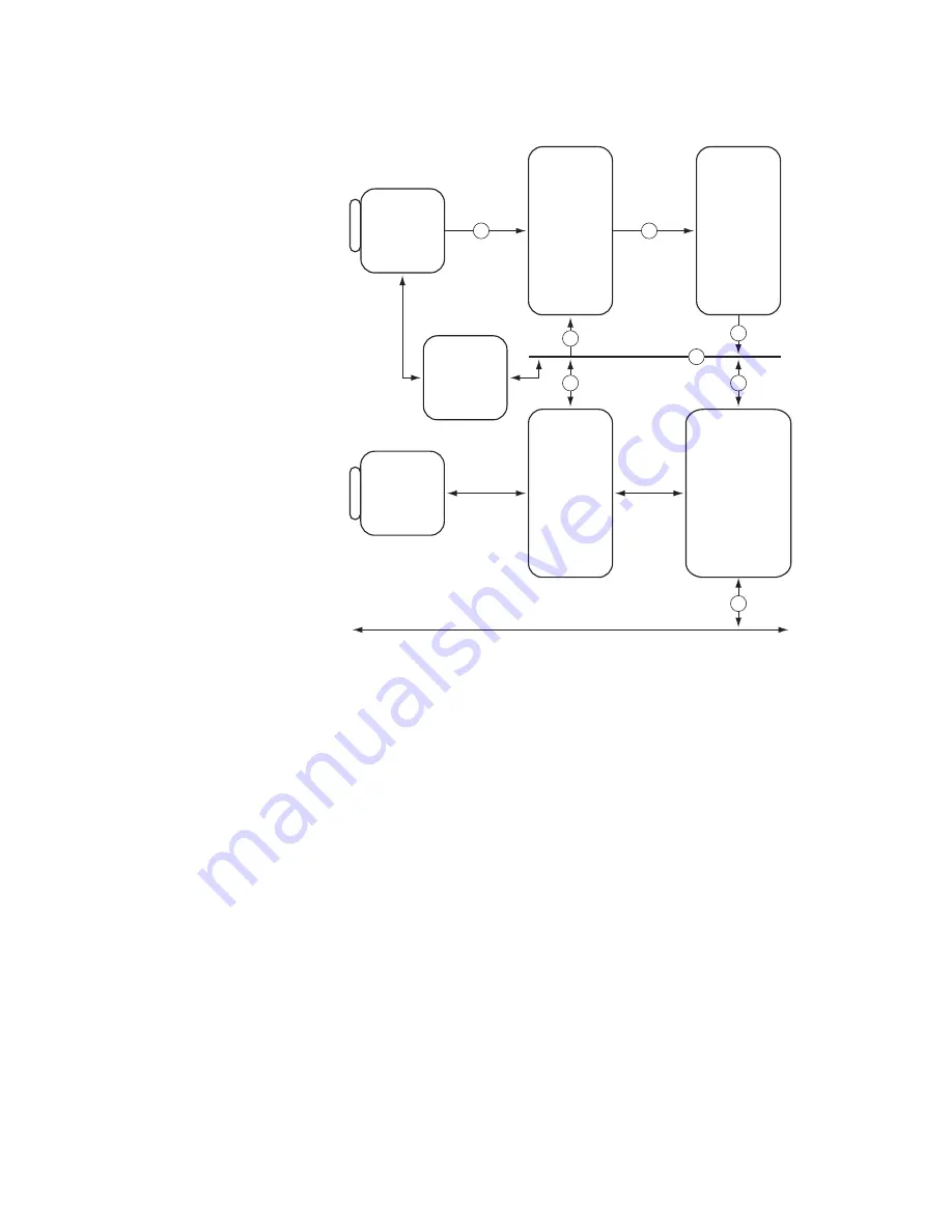
Figure 1-5 Base CL Virtual Frame Grabber
The Base CL VFG implements the Camera Link base configuration, i.e. it can accept a
single camera putting out up to 24 bits of data.
The Base CL VGF can accept input data at up to 85 Mhz.
The following paragraphs are a short description of each block.
The Camera Link Interface block implements the CL base configuration This block has
the Channel Link IC, the Camera Control drivers and the serial communication tran-
ceivers.
The MUX block packs and assembles the data from the Camera Link block before it is
pushed into the FIFO. This block re-arranges on-the-fly the data from the camera’s
taps so that the data is written in raster scan format in the host memory.
The FIFO block, ?? Kilobytes deep, decouples the camera from the DMA engine. It is
implemented with dual ported memories.
24
64
64
64
64
64
64
64
Camera Link
Interface
MUX
Video Pipeline,
Data Packer
PCI Interface,
Scatter-Gather
DMA Engine
Camera
Control,
CTABs
FIFO
?? KB
I/O,
Triggers,
Encoders
UART
Serial
Interface
??
Local Bus
PCI Express Bus
CL1
Summary of Contents for KBN-CL4-2.51-SP
Page 20: ...P r e l i m i n a r y The Karbon CL Models The Karbon KBN 1 12 BitFlow Inc Version F 0 ...
Page 62: ...P r e l i m i n a r y DEST_ADD The Karbon KBN 3 8 BitFlow Inc Version F 0 ...
Page 190: ...P r e l i m i n a r y Camera Link Controls CCs The Karbon KBN 7 12 BitFlow Inc Version F 0 ...


