CB-100-1
65
7
Data communication with the VARIPACK frequency
inverter
7.1
Communication via the BEST software
Information
The requirement for installing and using the
BEST software is a PC or a mobile device
equipped with Windows XP or a later version.
Communication with the VARIPACK frequency
inverter for devices without Windows operating
system is only possible via the optional control
panel (see chapter Removable control panel
(with display and keypad), page 66).
The BEST software offers comprehensive access to all
operating data and control parameters and can be
downloaded for free from the BITZER website
(www.bitzer.de).
The data link and communication with the BEST soft-
ware can take place via:
• BEST interface converter.
• Direct Ethernet connection.
• Ethernet connection through router/GSM.
BEST interface converter (using RJ12 cable)
• Part number 344 314 01.
• Requirements: PC/mobile device equipped with USB
interface.
• Restrictions: no firmware update possible.
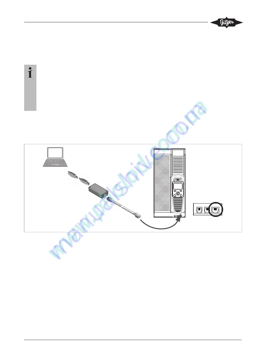
Connecting the BEST interface converter:
• Plug the BEST interface converter into the right
socket (XC3) on the underside of the interface exten-
sion of the VARIPACK frequency inverter using the
RJ12 cable (see figure 18, page 65).
BEST
Software
BEST
Converter
XC1 XC2 XC3
RJ12
Fig. 18: Connecting VARIPACK via BEST interface converter and RJ12 cable with a PC/mobile device
Direct Ethernet connection (using RJ45 network cable)
• Requirements: PC/mobile device equipped with Eth-
ernet socket (RJ45).
• A standard network cable is sufficient, no crossed
cable being necessary.
Ethernet connection through router/GSM
• Requirements: PC or mobile device with network ac-
cess.
• Local or worldwide access when connected to the In-
ternet via a router/GSM.
Connecting the Ethernet network cable (see figure 19,
page 66):
• Plug the network cable into the VARIPACK control
module at the top.
• To disconnect the cable, the control panel must be
dismounted (see figure 7, page 46, position 1).
• Next, introduce a screwdriver from the front and
press it slightly downwards, in order to unlock the
clip of the network cable.
Summary of Contents for VARIPACK FDU+12
Page 12: ...CB 100 1 12 1 2 3 4 Abb 7 Steuremodul abmontieren...
Page 46: ...CB 100 1 46 1 2 3 4 Fig 7 Dismounting the control module...
Page 70: ...Notes...
Page 71: ...Notes...


