10
/
33
9
DI1
Digital Input 1
B1
10
GND
CH 1 RS232 GND
11
RXD1
CH 1 RS232 RX
DI2/TTL/PI0
12
TXD1
CH 1 RS232 TX
DI3/TTL/PI1
13
VDD_OUT
Power VDD Output
(12V)
14
GND
Power GND
15
ADC0
CH 0 analog input
16
ADC1
CH 1 analog input
DO0
17
ADC2
CH 2 analog input
DO1
18
NC
NULL (reserved)
ADC3
19
K0+
CH 0 Relay K0+
20
K0-
CH 0 Relay K0-
21
K1+
CH 1 Relay K1+
22
K1-
CH 1 Relay K1-
1.5.2 Definition of Cables
TG501 utilizes industrial terminal block, so we suggest you use materials of cable 28-16AWG.
Definition of cable for power and RS232 are as below.
1)
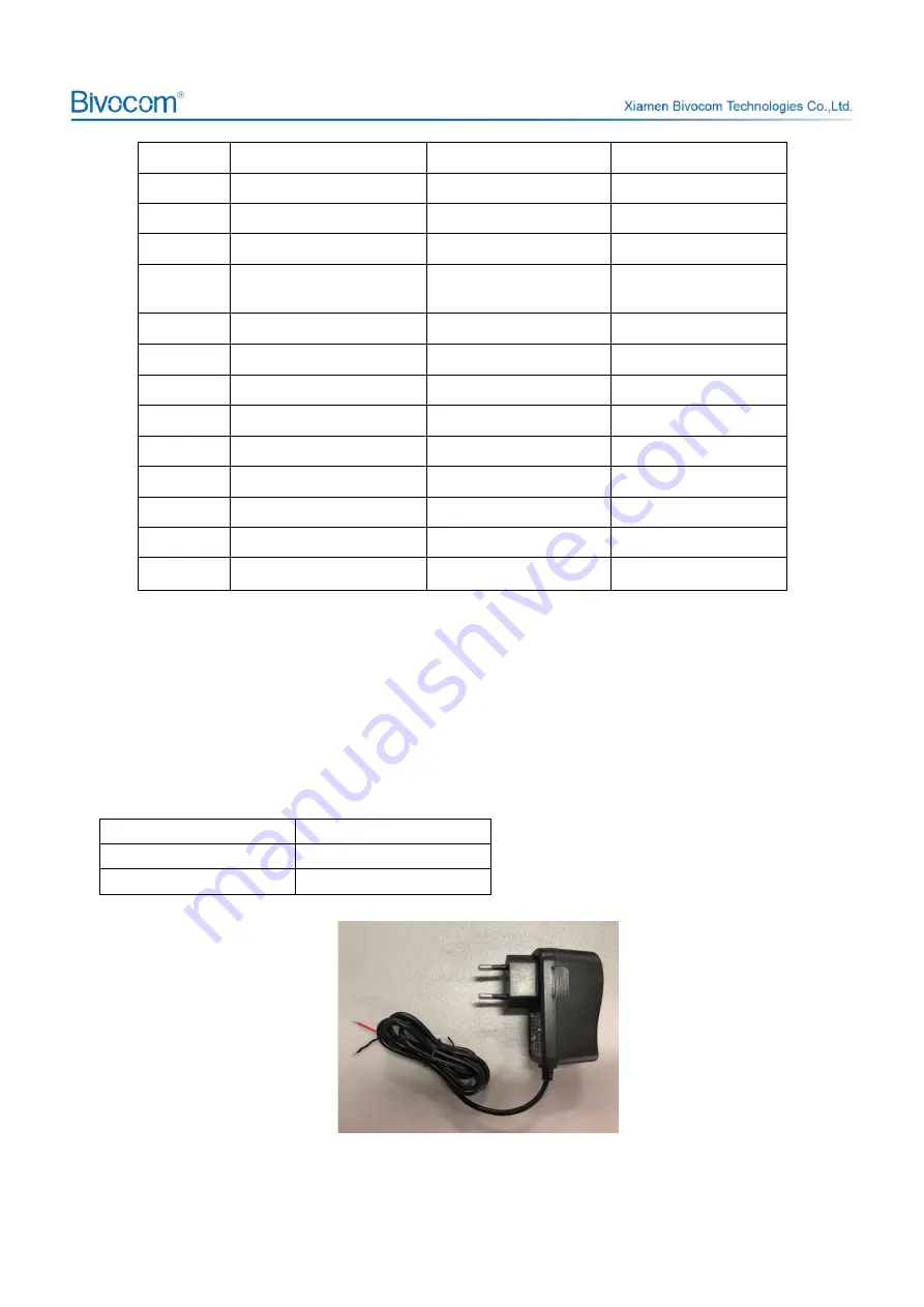
Power Adapter (Output 12VDC/1.5A)
Color of cable
Power Output Polarity
Red
VIN+( Anode)
Black
VIN-( Cathode)
Figure 4: power adapter


