◈
Information
This Installation Guide includes a brief outline of information necessary for product
installation. For more detailed installation information, please refer to the user manual in the
enclosed CD. The contents of the CD include the following.
1. Manual: User Manual, Code Chart, Control Commands
2. Drivers: Windows Drivers, OPOS Drivers
3. Utilities: a logo download tool and a virtual memory switch control tool
We at BIXOLON maintain ongoing efforts to enhance and upgrade the functions and quality
of all our products. In following, product specifications and/or user manual content may be
changed without prior notice.
◈
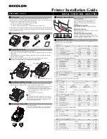
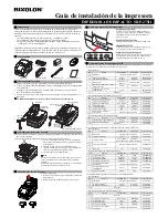
Components
SRP-275II
Ribbon Cartridge
Paper Roll
CD
AC/DC Adaptor
Power Code
Installation Guide
◈
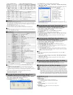
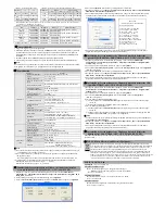
Connecting the cables
1. Turn off the printer and the host ECR (host computer).
2. Plug the power cord into the Adaptor, and then plug the Adaptor into the power connector
of the printer.
3. Check the interface cable (Serial, Parallel, USB, or Ethernet), and connect the interface
connector cable accordingly.
4. Plug the drawer kick-out cable into the drawer kick-out connector on the printer.
※
Do not use an adapter that was not supplied with the printer.
◈
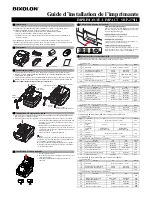
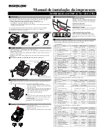
Installing the Ribbon Cartridge
1. Before inserting the ribbon cartridge, turn the knob clockwise to prevent twisting of the ribbon.
2. Open the front cover of the printer and remove the old ribbon cartridge, if any.
3. Insert the ribbon cartridge as shown in the figure so that
the ribbon is aligned to the rear of the printer head.
4. To allow the ribbon to move freely within the cartridge
when inserting the ribbon cartridge, turn the knob
clockwise once more.
5. Close the front cover of the printer.
※
Note
Using unauthorized ribbon cartridges may result in poor
printing quality or malfunction and will void the warranty.
Refer to the product specifications in this guide to learn
more about the ribbon cartridge.
◈
Installing the Paper Roll
1. Open the rear cover.
2. Insert a new paper roll, making sure to align it properly.
3. Pull out a small amount of paper, and close the cover.
◈
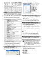
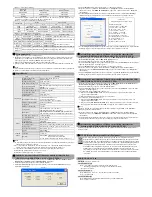
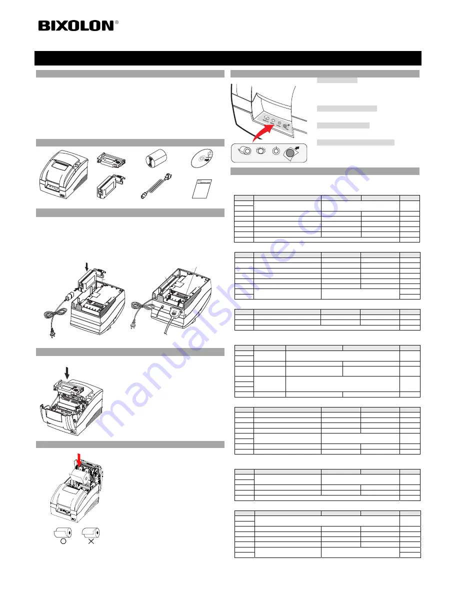
Using the Operation Panel
•
FEED (Feed button)
Press the FEED button once to discharge extra
paper. Holding down the FEED button will
discharge paper continuously until the button is
released.
•
POWER (Power, Green LED)
When turning on the power, a green LED will be
lit.
•
ERROR (Error, Red LED)
When an error occurs, a red LED will be lit. (e.g. no
paper, cover ajar, etc.)
•
PAPER OUT (Out of paper, Red LED)
The paper LED will be red when the paper roll is
running low. If there is no paper left, the paper LED
will be on together with ‘Error’ LED.
◈
Setting the DIP Switches
Changing Dip Switch settings must be done when the printer is off. Any changes done while
the printer is on will not be processed.
• DIP Switch 1
SW
Function
ON
OFF
Default
1-1
Emulation
Refer to the following table 1
OFF
1-2
1-3 Auto
Cutter
Enable
Disable
ON
1-4
Compatible with SRP-275 Enable
Disable
OFF
1-5
Serial Interface
Memory Switch
DIP Switch
OFF
1-6
Printing NV bit image after cutting
Enable
Disable
OFF
1-7
Near-End Sensor Status
Enable
Disable
ON
1-8 Undefined OFF
• DIP Switch 2 (RS232C Serial Interface Model)
SW
Function
ON
OFF
Default
2-1
Data Receive Error
Ignore
Print “?”
OFF
2-2
Black Mark Sensor
Enable
Disable
OFF
2-3 Handshaking
XON/XOFF
DTR/DSR
OFF
2-4
Data Length
7 bits
8 bits
OFF
2-5 Parity
Check
Enable
Disable
OFF
2-6 Parity
Selection
EVEN
ODD
OFF
2-7
Baud Rate Selection
Refer to the following table 2
OFF
2-8
OFF
• DIP Switch 2 (Parallel Interface Model)
SW
Function
ON
OFF
Default
2-1
Auto Line Feed
Enable
Disable
OFF
2-2
Black Mark Sensor
Enable
Disable
OFF
2-3~8 Undefined OFF
(1) DIP Switch setting for Citizen (iDP 3550) Mode
• DIP Switch 1
SW
Function
ON
OFF
Default
1-1
Emulation
Refer to the following table 1
OFF
1-2
1-3 Auto
Cutter
Enable
Disable
OFF
1-4
CBM
command
CBM2 Mode
(iDP3530 System)
CBM1 Mode
(iDP3540 System)
OFF
1-5
International
Character
Refer to the following table 3
ON
1-6
1-7
1-8 CR
Mode
CR
CR+LF
OFF
• DIP Switch 2 (RS232C Serial Interface Mode)
SW
Function
ON
OFF
Default
2-1 Data
Length
8bits
7bits
ON
2-2 Parity
Check
Disable
Enable
ON
2-3 Parity
Selection
ODD
EVEN
ON
2-4 Handshaking
DTR/DSR
XON/XOFF
ON
2-5
Baud Rate Selection
Refer to the following table 2
OFF
2-6
2-7
Near-End Sensor Status
Enable
Disable
OFF
2-8 Mechanism
Type
Graphic
Text
OFF
(2) DIP Switch setting for Star (SP500) Mode
• DIP Switch 1
SW
Function
ON
OFF
Default
1-1
Emulation
Refer to the following table 1
OFF
1-2
1-3 Auto
Cutter
Enable
Disable
OFF
1-4
Printing in Black/Red
Enable
Disable
OFF
1-5~8 Reserved OFF
• DIP Switch 2 (RS232C serial interface model)
SW
Function
ON
OFF
Default
2-1
Reserved OFF
2-2
2-3 Handshaking
XON/XOFF
DTR/DSR
OFF
2-4 Data
Length
7bits
8bits
OFF
2-5 Parity
Check
Enable
Disable
OFF
2-6 Parity
Selection
EVEN
ODD
OFF
2-7
Baud Rate Selection
Refer to the following table 2
OFF
2-8
OFF
Printer Installation Guide
KN02-00005A (Rev.1.4)
IMPACT PRINTER SRP-275II
Adaptor
Power connector
Power cord
Drawer kick-out
connector
Interface connector
Drawer
kick-out
cable
Interface cable
(Serial/Parallel/USB/Ethernet)
PAPER OUT ERROR
POWER
FEED