


Rev. 1.00
- 61 -
SRP-275II
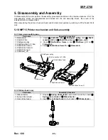
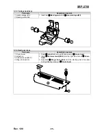
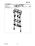
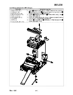
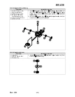
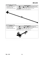
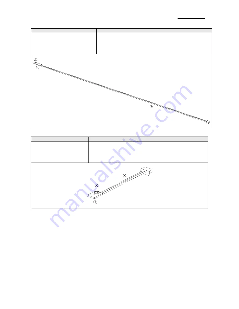
5-1-15 BMS-B assy
Part name
Assembly procedure
PCB
①
-BMS-B
②
Photo-Interrupter
③
Harness-BMS-B
1. Insert
②
Photo-Interrupter
to
PCB
①
-BMS-B.
.
2. Solder the land on
PCB
①
-BMS-B
bottom side and attach
③
Harness-BMS-B
on the land.
<Check point>
After soldering, check the frozen lead and short.
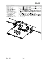
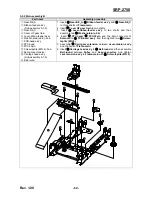
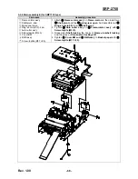
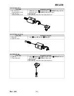
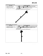
5-1-16 BMS assy
Part name
Assembly procedure
PCB
①
-BMS
②
Photo-Interrupter
③
Harness-BMS
1. Insert
②
Photo-Interrupter
to
PCB
①
-BMS.
.
2. Solder the land on
PCB
①
-BMS
bottom side and attach
③
Harness-BMS-B
on the land.
<Check point>
After soldering, check the frozen lead and short.


