background image


Rev. 1.00 

- 76 -

SRP-275II

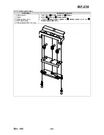
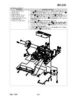
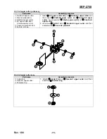
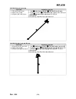
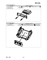
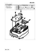
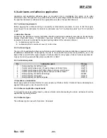
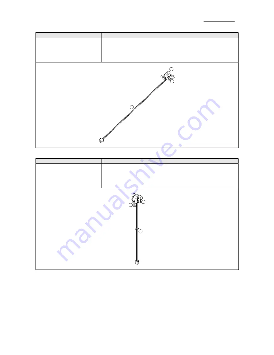
5-4-5 Switch-cover open assy 

Part name 

Assembly procedure 

 PCB

-switch-cover open 

 Switch

-micro (5.9gf) 

 Harness

-switch-cover open 

1. Insert 

 Switch

-micro (5.9gf)

 to 

 PCB

-Switch-cover open

2. Solder the land on 

 PCB

-Switch-cover open

 bottom side and 

attach 

 Harness

-Switch-cover open 

on the land. 

<Check point> 

After soldering, check the frozen lead and short. 


1

2

3


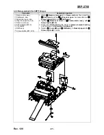
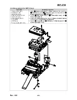
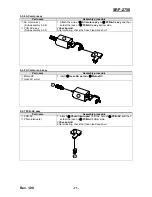
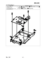
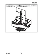
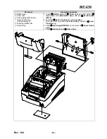
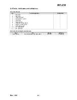
5-4-6 Switch-paper near end -W assy 

Part name 

Assembly procedure 


PCB-switch-paper near end-W 

 Switch

-micro (5.9gf) 


Harness-switch-paper near end 

1. Insert 

 Switch

-micro (5.9gf)

 to 

 PCB

-Switch-paper near end-W

.

2. Solder the land on 

 PCB

-Switch-paper near end-W

 bottom side 

and attach 

 Harness

-Switch-paper near end-W 

on the land. 

<Check point> 

After soldering, check the frozen lead and short. 


2

1

3


Summary of Contents for SRP-275II

Page 1: ...Service Manual SRP 275II Impact Printer Rev 1 00 http www bixolon com ...

Page 2: ...ppearance 31 3 1 1 Printer Dimensions mm 31 3 1 2 AC Adapter Dimensions mm 31 3 1 3 Feature Locations 32 3 2 General Specifications 33 3 3 Reference information 34 3 3 1 Printer Mechanism Specification 34 3 3 2 Printing Specification 34 3 3 3 Character Specification 36 3 3 4 Paper Specification 37 3 3 5 Ribbon Cassette Specification 39 3 3 6 Environment Conditions 40 3 3 7 Reliability 41 3 3 8 Cer...

Page 3: ...unit Main assembly 63 5 2 1 Main assembly A 63 5 2 2 Main assembly B 64 5 2 3 Main assembly C 65 5 2 4 Main assembly D 66 5 2 5 Main assembly E for SMP715A type 67 5 2 6 Main assembly E for SMP715C type 68 5 3 Auto cutter unit assembly 69 5 3 1 AC timing belt assy 69 5 3 2 AC upper frame caulking assy 69 5 3 3 AC upper cutter guide assy 70 5 3 4 AC upper cutter assy 70 5 3 5 AC motor assy 71 5 3 6...

Page 4: ...on requirements 90 6 3 5 Adhesive types 90 6 4 Tools lubricants and adhesives 91 6 4 1 List of tools 91 6 4 2 List of lubricants and adhesives 91 7 Troubleshooting 92 7 1 Troubleshooting flow chart 92 A POWER LED does not light 93 B PAPER LED is lit 94 C ERROR LED is blink 95 D ERROR LED is lit 96 E Self test is not normal 97 F Data from host is not printed normally 98 7 2 Troubleshooting flow tab...

Page 5: ... Printer is a microprocessor based system using a 32 bit microprocessor This Service Manual provides the technical information for many individual component systems circuits and gives an analysis of the operations performed by the circuits If you need more technical information please contact our service branch or R D center Schematics and specifications provide the needed information for the accu...

Page 6: ...gs in the AC outlet and repeat the test 5 Design Alteration Warning Never alter or add to the mechanical or electrical design of the Receipt Printer Unauthorized alterations might create a safety hazard Also any design changes or additions will void the manufacturer s warranty 6 Components parts and wiring that appear to have overheated or that are otherwise damaged should be replaced with parts t...

Page 7: ...instrument chassis ground before connecting the positive lead always remove the instruments ground lead last 1 3 Precaution for Electrostatically Sensitive Devices ESDs 1 Some semiconductor solid state devices are easily damaged by static electricity Such components are called Electrostatically Sensitive Devices ESDs examples include integrated circuits and some field effect transistors The follow...

Page 8: ...ible because the paper feeding pitch is selectable High general control utility based on the BXL POS TM standard The head can be driven due to the internal drawer interface Character font 7ⅹ9 9ⅹ9 is selectable The auto cutter uses a circular method with a high quality blade and a long life Approximately 1 500 000 cuts Paper near end Switch is standard A internal AC adaptor Please be sure to read t...

Page 9: ...tor Interface connector Serial Parallel USB Ethernet Interface cable Drawer kick out cable 1 Turn off printer and the host ECR host computer 2 Plug the interface cable into the interface connector on the printer then fasten the screw on both sides of the connector 3 Plug the drawer kick out cable into the drawer kick out connector on the printer When removing the drawer kick out cable press on the...

Page 10: ...ttention to the placement of the ribbon in front of the Printer Head 5 During inserting the ribbon cassette turn the knob clockwise again to make sure the ribbon moves freely in the cassette 6 Close front cover of printer NOTES Malfunctions and other problems may arise if other than specified ribbon cassettes are used in the printer The Warranty may be void if other than specified ribbon cassettes...

Page 11: ...rrow mark back 3 Remove the used paper roll core if there is one 4 Insert the paper roll as shown 5 Be sure to note the correct direction that the paper should come off the paper roll 6 Pull out small amount of paper as shown Then close the cover and tear off the extra paper by pulling it toward the front of the printer CAUTION Do not touch the auto cutter blade when you open rear cover ...

Page 12: ...er and attach the Bracket hanger to the Frame base then tighten four screws 2 Attach the Bracket mount to the wall firmly with the eight screws Be sure that the Bracket attached properly to match the direction of arrow as shown And the Bracket mount should be always fixed vertically 3 Insert the Bracket hanger of Set to the Bracket mount as shown ...

Page 13: ...er 2 If you see this light blinking turn off the printer for a few seconds and then turn it back on If the light is still blinking call your supervisor or a service person PAPER OUT LED Red Color When this indicator light is on it means that the paper near end Replace the new paper roll When ERROR and PAPER OUT indicator lights are on it means paper end Install the paper roll See Installing paper ...

Page 14: ...ase1 The auto cutter does not work correctly Recovers by error recovery command Home position detection error This is Mechanical error Case 2 The home position cannot be detected due to a paper jam Case1 1000ms A Case2 300ms Recovers by error recovery command Errors that are impossible to recover Error Description ERROR LED blinking pattern Recovery R W error in memory or gate array After R W chec...

Page 15: ...B 26 02 40 40 1B 25 01 1B 63 34 00 1B c 4 41 42 43 44 45 46 47 48 A B C D E F G H Online Hex Dump Completed A period is printed for each code that has no ASCII equivalent 5 When the printing finishes turn off the printer 2 2 4 The self Test Mode The self test let you know if your printer is operating properly It checks the printing quality ROM version DIP Switch settings memory switch settings and...

Page 16: ...89 ABCDEFGHIJKLMNOPQRS 0123456789 ABCDEFGHIJKLMNOPQRST 0123456789 ABCDEFGHIJKLMNOPQRSTU 0123456789 ABCDEFGHIJKLMNOPQRSTUV 0123456789 ABCDEFGHIJKLMNOPQRSTUVW 123456789 ABCDEFGHIJKLMNOPQRSTUVWX 23456789 ABCDEFGHIJKLMNOPQRSTUVWXY 3456789 ABCDEFGHIJKLMNOPQRSTUVWXYZ 456789 ABCDEFGHIJKLMNOPQRSTUVWXYZ 56789 ABCDEFGHIJKLMNOPQRSTUVWXYZ 6789 ABCDEFGHIJKLMNOPQRSTUVWXYZ 789 ABCDEFGHIJKLMNOPQRSTUVWXYZ 89 ABCDE...

Page 17: ...rial interface model Switch Function ON OFF Default 2 1 Data receive error Ignore Print OFF 2 2 Black mark Sensor Enable Disable OFF 2 3 Hand shaking XON XOFF DTR DSR OFF 2 4 Word length 7 bits 8 bits OFF 2 5 Parity check Enable Disable OFF 2 6 Parity selection EVEN ODD OFF 2 7 OFF 2 8 Baud rate selection 2 Refer to the following table OFF DIP Switch 2 Parallel interface model Switch Function ON O...

Page 18: ... selection 3 Refer to the following table OFF 2 7 Near end switch Enable Disable OFF 2 8 Mechanism type Graphic Character OFF NOTES 1 Emulation Selection DSW 1 1 and 1 2 Emulation 1 1 1 2 BXL POS OFF OFF BXL POS KP ON ON STAR OFF ON CITIZEN ON OFF BXL POS KP Kitchen Printer mode A alarm is generated by printer after auto cutting and in paper end error 2 International Character Selection No Country...

Page 19: ... OFF 2 8 Baud rate selection 2 Refer to the following table OFF NOTES 1 Emulation Selection DSW 1 1 and 1 2 Emulation 1 1 1 2 BXL POS OFF OFF BXL POS KP ON ON STAR OFF ON CITIZEN ON OFF BXL POS KP Kitchen Printer mode A alarm is generated by printer after auto cutting and in paper end error 2 Baud rate selection Transmission speed Transmission 2 7 2 8 2400 baud ON ON 4800 baud OFF ON 9600 baud OFF...

Page 20: ...prevent an electric short which can damage the printer 1 Make sure the printer is turned off 2 Remove the screw from the DIP Switch cover Then take off the DIP Switch cover which is shown in the illustration below 3 Set the switches using a pointed tool such as tweezers or a small 4 Replace the DIP Switch cover Then secure it with the screw NOTES The new settings take effect when you turn on the p...

Page 21: ...8 Code page selection 1 Refer to the following table NOTES Desired code page can be selected using Memory Switch 2 4 8 by setting as following 1 Code page selection MSW 2 8 MSW 2 7 MSW 2 6 MSW 2 5 MSW 2 4 Character Table 0 0 0 0 0 Page 0 PC437 U S A 0 0 0 0 1 Page 1 Katakana 0 0 0 1 0 Page 2 PC850 Multilingual 0 0 0 1 1 Page 3 PC860 Portuguese 0 0 1 0 0 Page 4 PC863 Canadian French 0 0 1 0 1 Page ...

Page 22: ...5 to Off MSW 8 8 When Off is selected a bit of the automatic recoverable error in each status that is transmitted from the printer is changed every time the rear cover is open When On is selected a bit of the mechanical error in each status that is transmitted from the printer is changed every time the rear cover is open The setting of MSW 8 5 and 8 8 can be set by Memory Switch setup mode Customi...

Page 23: ...Turn the power on while pressing the paper FEED button 3 Press the FEED button twice while POWER ERROR and PAPER OUT LEDs are lit 4 Close the cover The printer prints the enabled settings of the Memory Switches and instructions 5 Follow the instructions to process the switch setup NOTES In the Memory Switch setup the power LED may be flashing Example of Memory Switch setup sheet Memory S W Setup Y...

Page 24: ...ing 8 bits 7 bits NO NO NO NO NO YES YES YES YES NO NO YES YES NO NO NO YES YES NO Resetting Buffer full release condition Current setting 640 bytes 522 bytes NO Resetting Cover open status Current setting Paper out Cover open Finishing Memory S W Setting Mode YES Memory S W Setting Completed NO YES YES NO NO YES YES YES NO NO YES YES Finishing Memory S W Setting Mode Finishing Memory S W Setting ...

Page 25: ...1 n2 n3 0n4 0 n1 n2 n3 n4 8 Data definition clear specified bit Definition n1 n2 n3 0n4 0 n1 n2 n3 n4 8 Data Definition clear all data Definition Fixed at 0000 Definition data write and reset Write W Fixed at 0000 Definition data write and reset and test print Write T Fixed at 0000 Ex Memory Switch 1 8 0 Memory Switch 2 7 1 Memory Switch 2 A 1 for a test print PRINT 1 CHR H1B CHR H1D CHR H23 CHR H...

Page 26: ...ountries Chinese character specifications DBCS Standard Specifications SBCS Memory Switch Number Ex factory Settings n1 n2 n3 n4 MSW 0 0000 MSW 1 0000 MSW 2 0000 MSW 3 0000 MSW 4 0000 MSW 5 0000 MSW 6 0000 MSW 7 0000 MSW 8 0000 Chinese character specifications DBCS For China Memory Switch Number Ex factory Settings n1 n2 n3 n4 MSW 0 0010 MSW 1 0000 MSW 2 0000 MSW 3 0000 MSW 4 0000 MSW 5 0000 MSW 6...

Page 27: ...printing ESC 4 Red white black inversion printing ESC 5 Red white black inversion printing cancelled When using ESC 5 to cancel adornments it returns to the previously set adornments Adornments such as underline upper line double tall expanded and enhancing are cancelled if there is no command to set them for example the ESC 1 specification for underlines This setting is enabled only for ANK chara...

Page 28: ...ual Auto cut Function 1 Disabled Enabled 2 1 0 Near end switch Function 2 Refer to the following table NOTES 1 Contextual Auto cut Function This function auto cuts paper when a paper feed command that feeds continuously over 7 6 inch Hosts that cannot send an escape sequence such as ESC d 0 can cut paper if a 1 6 inch line feed code LF is sent seven times 2 Near end switch Function When an optiona...

Page 29: ...863 Canadian French 0 0 1 0 1 Page 5 PC865 Nordic 0 0 1 1 0 Page 16 WPC1252 Latin1 0 0 1 1 1 Page 17 PC866 Russian 0 1 0 0 0 Page 18 PC852 Latin2 0 1 0 0 1 Page 19 PC858 Euro 0 1 0 1 0 Page 21 PC862 Israel 0 1 0 1 1 Page 22 PC864 Arabic 0 1 1 0 0 Page 23 Thai character code 42 0 1 1 0 1 Page 24 WPC1253 Greek 0 1 1 1 0 Page 25 WPC1254 Turkish 0 1 1 1 1 Page 26 WPC1257 Baltic 1 0 0 0 0 Page 27 Farsi...

Page 30: ...ction Disabled Enabled 7 4 3 ESC RS a n command function Only Setting Auto status sent only once 2 1 0 Data reception error serial Prints Ignored Memory Switch 5 Bit Function 0 1 F 0 Reserved Memory Switch 6 Bit Function 0 1 F 0 Reserved Memory Switch 7 Bit Function 0 1 F 0 Reserved ...

Page 31: ... Product Specifications 3 1 Appearance 3 1 1 Printer Dimensions mm SRP 275IIA Type SRP 275IIC Type Approx wt 2 4 kg Shipping Wt 3 9 kg Approx wt 2 5 kg Shipping Wt 4 0 kg 160 239 157 157 239 160 3 1 2 AC Adapter Dimensions mm ...

Page 32: ...Rev 1 00 32 SRP 275II 3 1 3 Feature Locations SRP 275IIA Type SRP 275IIC Type 1 2 3a 4 5 6 1 2 3b 4 5 6 ...

Page 33: ...ide The flow control Baud rate Stop bit and Parity are determined by DIP Switch position Parallel interface IEEE 1284 Mode Forward mode Compatibility mode Reverse mode Nibble Byte mode Connector Self powered USB Transfer type BULK Speed 480 Mbps High Speed Power Self Powered Printer Printing method 9pins serial impact Printing speed 5 1 lines sec Auto cutter Type Rotary Cutting method 1 point part...

Page 34: ...lity Approx 18 million print lines Head life Approx 300 million dots wire Weight Approx 1 1kg Excluding ribbon cassette auto cutter 3 3 2 Printing Specification Item Description Remark Printing method Serial impact dot Head wire configuration 9 pin serial type 1 Dot pitch 0 352mm 1 72 Dot wire diameter 0 28mm 0 01 Printing direction Bidirectional with logic seeking Line feed 4 233mm 1 6 default se...

Page 35: ...racter Set Character dimensions W H Dot spacing between characters Characters per line cpi Characters per inch cpi ANK 1 2 3 1mm 047 122 3 half dots 40 16 7 9 Graphics 1 7 3 1mm 070 122 0 40 16 ANK 1 6 3 1mm 063 122 3 half dots 33 13 3 9 9 Graphics 2 0 3 1mm 079 122 0 33 13 3 ANK 1 2 3 1mm 079 122 2 half dots 42 17 8 7 9 Graphics 1 6 3 1mm 063 122 0 42 17 8 ANK 1 6 3 1mm 063 122 2 half dots 35 14 ...

Page 36: ... 1 7ⅹ3 2 1 4ⅹ3 2 5 7ⅹ3 0 Column interval mm 2 13 1 59 3 19 Line interval 1 6 1 6 1 3 Character sets Alphanumeric characters 95 International characters 48 Extended graphics 128 x 27 pages Character structure 7 9 with 400 half dot positions per line 9 9 with 400 half dot positions per line NOTES 1 Character size 7 9 font example 2 41mm 0 095 0 014 0 352mm 0 159mm 0 006 0 123 3 12mm 1 25mm 0 049 1 5...

Page 37: ... mark the area indicated with B GretagMacbeth density meter D19C used 3 3 4 1 Black mark paper C Type With autocutter It shows the dimensions of the black mark when the receipt length is 127mm The black mark must be printed in one place in a receipt either on the right or left of the face or the reverse side A To avoid cutting preprinted material by mistake this area must not be preprinted B To av...

Page 38: ...ion 5 of the GS E command D Minimum distance of the black marks If you use the receipt with a length other than 127mm the distance between the black marks must be more than 65mm 3 3 4 2 Black mark paper C Type Without autocutter It shows the dimensions of the black mark when the receipt length is 127mm The black mark must be printed in one place in a receipt either on the right or left of the face...

Page 39: ...ns of print density for the black mark Density print of the black mark 1 0 or more Density of the non black mark 0 1 or less GretagMacbeth density meter DensiEye 700 filter Unpolarized used 3 3 5 Ribbon Cassette Specification Item Description Remark Model RRC 201 B R Color Black Red Size 13 mm W ⅹ6 mm L Life 1 Black 1 5 million characters with continuous printing at 25 77 Red 750 000 characters wi...

Page 40: ...RH Non condensing Storage 10 90 RH Non condensing Shipping 5 90 RH Non condensing except paper and ribbon Vibration resistance When packed Frequency 5 to 55Hz Acceleration 5G Sweep 10 minutes half cycle Duration 1 hour Direction x y and z Impact resistance When packed Package SRP 275II standard package Height 60cm 23 62 Directions 1 corner 3edges and 6 surfaces When unpacked Height 5cm 1 97 Direct...

Page 41: ...he Carriage Motor 3 Head_7 Print Head Pin 7 21 CM_PHASE2 Phase control of the Carriage Motor 4 Head_1 Print Head Pin 1 22 CM_I02 Control Input of the Carriage Motor 5 Head_5 Print Head Pin 5 23 CM_I12 Control Input of the Carriage Motor 6 Head_3 Print Head Pin 3 24 GND Ground 7 VPP24V0 Voltage for Driving Print Heads 25 PM_PHASE1 Phase control of the Carriage Motor 8 VPP24V0 The Voltage for Drivin...

Page 42: ...d on time Platen Gap 0 40 0 50mm Max frequency 1500Hz Performance Forms capability Original 2 copies Max operating temp 90 Temperature Max transient temp 110 For 5 minutes 25 duty 3 3 11 Printer Head Thermistor Specification Item Description Remark Type NTC F CHIP FF103J Electronic Characteristics Resistance R25 10 5Ω At 25 β Value 3950K 2 Temperature strage 30 125 Rx formula Exp 4 864010225 4344 ...

Page 43: ...oltage 24VDC 10 Current 0 4A mean 1 6A peak 3 3 15 Switch Sensor Specification Item Description Remark Paper end switch Micro switch MIC Paper near end switch Micro switch MIC Cover open switch Micro switch MIC Black mark sensor Photo interrupter sensor 3 4 SMPS Specifications 3 4 1 SMPS Switching Mode Power Supply Specification Item Description Remark Input voltage 100VAC 240VAC Input current Max...

Page 44: ...ing Flow control H W DTR DSR S W XON XOFF XON ASC code 11 XOFF ASC code 13 Signal level Logic 1 MARK 3V 15V Logic 0 SPACE 3V 15V Baud rate 19200 2400 4800 9600 bps Data word length 7 bit 8 bit Parity None Even Odd Connector DB25P female I F PBA NOTES The handshaking Flow control Data word length Baud rate Parity functions depend on the DIP Switch settings Refer to the Service manual 3 5 1 b RS 232...

Page 45: ...CE Logic 0 The printer is not busy The host transmits a data to the printer after confirmi ng this signal When XON XOFF flow control is selected the host does not check this signal 3 5 1 e H W Flow Control When DTR DSR flow control is select before transmitting a data the Printer checks whether the host is BUSY or not If the host is BUSY the Printer does not transmit a data to the host If the host...

Page 46: ...ntrol lines in units of bits Nibble In the Byte mode data transmission are proceeded by making the 8 bits data lines bidirectional Neither mode can operate at the same time as the compatibility mode so switching is always required 3 5 2 c Signal Specification Compatibility Nibble Byte mode Pin no Source Compatibility mode Nibble mode Byte mode 1 Host nStrobe HostClk HostClk 2 Host Printer Data 0 L...

Page 47: ...uffing after 6 ones Transceiver Differential receive sensitivity 200 mV Differential common mode range 0 8 2 5 V Single end receiver threshold 0 8 2 0 V Speed 480 Mbps High Speed Power Self powered Cable connector Cable 5m 2m Connector A B type Other Support USB spec V2 0 Hi speed 3 5 3 b Signal Description Pin No Signal name Assignment Color Function Shell Shield Drain wire Frame ground 1 VBUS Re...

Page 48: ...RP IP mode Static IP DHCP Dynamic Host Configuration Protocol RX buffer 32 KByte Flow control Hardware RTS CTS 3 5 4 b Ethernet I F cable 3 5 4 c Ethernet I F signal descriptions Pin No Signal name Assignment Color Function 1 TD White Orange Transmit 2 TD Orange Transmit 3 TCT White Green Receive 4 NC Blue 5 NC White Blue 6 RCT Green Receive 7 RD White Brown 8 RD Brown For more information refer t...

Page 49: ...k Out Specifications 3 6 1 Drawer Cable 3 6 2 Cable Connection Pin No Description Direction 1 Signal GND 2 Drawer kick out driver signal 1 Output 3 Drawer Open Close signal Input 4 24V 5 Drawer kick out driver signal 2 Output 6 Signal GND ...

Page 50: ... 1 Wiring Diagram 4 1 1 Main board wiring diagram ASSY PCB MAIN ASSY INTERFACE CN3 CN4 CN8 CN1 CN5 CN2 I F CN1 I F CN2 DRAWER A S S Y P C B C O N N E C T O R P O W E R S W I T C H ASSY PCB MECHA A S S Y P C B O P P A N E L CN7 SMPS HOST ...

Page 51: ... 2 C N 1 1 A S S Y P C B S W C O V E R O P E N A S S Y P C B S W P A P E R E N D ASSY PCB BMS ASSY AUTO CUTTER ASSY SW PAPER NEAR END_W ASSY SW PAPER NEAR END ASSY PCB CONNECTOR ASSY MAIN PCB CN502 CN504 CN505 CN501 CN503 ASSY PCB MECHA SOLENOID HC MOTOR ASSY PCB MAIN ASSY FPC HEAD LF MOTOR ...

Page 52: ...Rev 1 00 52 SRP 275II 4 2 Block Diagram ...

Page 53: ...ft gear pulley Shaft reduction A C 2ea Shaft ribbon frame L Shaft ribbon frame R Shaft ribbon feed Shaft lever_CC 1 Caulk Shaft R F idle Shaft gear pulley two Shaft reduction A C and Shaft ribbon feed on Frame main 2 Caulk Shaft ribbon frame L and Shaft lever_CC on Frame main 3 Caulk Shaft ribbon frame R on Frame main Shaft lever_CC Frame main Shaft R F idle Shaft gear pulley Shaft reduction A C 2...

Page 54: ...nd Wave washer to Shaft reduction B and then grease Wave washer with HG 31S 3 Insert Gear re_B to Shaft reduction B and then fasten Washer plain ø2 6 to Shaft reduction B 5 1 4 Lever tension assy Part name Assembly procedure Lever tension belt Shaft pulley Pulley Washer plain ø2 6 1 Caulk Shaft pulley on Lever tension belt and then grease Shaft pulley with HG 31S 2 Insert Pulley to Shaft pulley an...

Page 55: ...riage WI 1 2 2 5 1 6 Head cover assy Part name Assembly procedure Cover head Label hot Screw manual M4 0 Ring e hole ø3 0 1 Paste Label hot on the left bottom side of Cover head 2 Insert Screw manual M4 0 into the right side hole of Cover head 3 Assemble Ring e hole ø3 0 onto the starting point of a spiral during adhering closely to Cover head 1 2 3 4 ...

Page 56: ...a Screw taptite M3 4 2ea 1 Tighten Frame holder basket L ass y to Frame basket with two Screw taptite M3 6 2 Tighten Frame holder basket R ass y to Frame basket with two Screw taptite M3 6 3 Insert two Roller holder to Shaft roller holder and then assemble two Spring roller holder to Shaft roller holder Frame holder basket L ass y and Frame holder basket R ass y 4 Insert Platen paper guide in Fram...

Page 57: ...a Screw taptite M3 4 2ea 1 Tighten Frame holder basket L ass y to Frame basket with two Screw taptite M3 6 2 Tighten Frame holder basket R ass y to Frame basket with two Screw taptite M3 6 3 Insert two Roller holder to Shaft roller holder and then assemble two Spring roller holder to Shaft roller holder Frame holder basket L ass y and Frame holder basket R ass y 4 Insert Platen paper guide in Fram...

Page 58: ...e holder basket L caulking ass y and then assemble Washer plain ø2 6 Check point Check Gear reduction to rotate smoothly 1 3 2 5 1 10 Frame holder basket L caulking assy Part name Assembly procedure Frame holder basket L Shaft locking Shaft reduction 1 Caulk Shaft locking and Shaft reduction on Frame holder basket L 1 2 3 5 1 11 Frame holder basket R caulking assy Part name Assembly procedure Fram...

Page 59: ...3 Cutter lower assy Part name Assembly procedure Cutter lower Frame housing cutter upper Spring cutter lower 2ea Frame housing cutter lower Screw taptite M3 4 2ea 1 Insert Cutter lower in Frame housing cutter upper and then insert two Spring cutter lower between Cutter lower and Frame housing cutter upper 2 Tighten Frame housing cutter upper to Frame housing cutter lower with two Screw taptite M3 ...

Page 60: ...Spring button between Arm open and Frame pivot locking R 5 Insert Frame clamshell locking between Frame pivot locking L and Frame pivot locking R and then insert Shaft clamshell locking Spring locking L and Spring locking R And assemble two Ring e hole ø2 5 to Shaft clamshell locking 6 Attach Holder platen ass y to Frame rotator and then insert Shaft housing platen into the hole of Frame rotator A...

Page 61: ...B BMS B bottom side and attach Harness BMS B on the land Check point After soldering check the frozen lead and short 5 1 16 BMS assy Part name Assembly procedure PCB BMS Photo Interrupter Harness BMS 1 Insert Photo Interrupter to PCB BMS 2 Solder the land on PCB BMS bottom side and attach Harness BMS B on the land Check point After soldering check the frozen lead and short ...

Page 62: ...ssembly procedure Holder platen Platen Rubber platen 3ea Bar holder platen Screw taptite M3 10 2ea 1 Insert three Rubber platen in Platen 2 Attach Platen to Holder platen 3 Tighten Bar holder platen to Holder platen with two Screw taptite M3 10 1 2 3 3 3 4 4 4 ...

Page 63: ...l sticker and Plate insulation on Frame main caulking ass y 2 Grease six shafts on Frame main caulking ass y with HG 31S 3 Insert Lever change color into Shaft lever_CC and then assemble Washer plain ø2 6 4 Insert Assy gear pulley and Gear RE_B to the Shaft gear pulley and Shaft R F idle and then assemble each of Washer plain ø2 6 5 Insert Spring solenoid between Solenoid and Lever change color an...

Page 64: ...o three shafts of Frame main 2 Insert Cover HF gear train to two shafts 3 Insert Lever ribbon feeder ass y to two shafts and then assemble two Washer plain ø2 6 4 Insert FPC head FPC 35pin and the 2pin connector of Solenoid to PCB head ass y and then tighten two Screw taptite M3 4 5 Assemble Spring lever tension between Lever tension ass y and the hook of Frame main 6 Insert Carriage head ass y to...

Page 65: ...ide and then insert Shaft head_guide into two holes of Frame main 3 Insert two Lever ad to the end of Shaft head_guide and then rotate two Lever ad downward And oil Shaft head_guide with G948P 4 Insert Shaft head carriage in two holes the Frame main and then assemble Ring e hole ø3 0 to Shaft Head carriage 5 Insert FPC head in Printer head and then tighten Printer head on Carriage head ass y with ...

Page 66: ...tor to the connector of PCB head ass y 2 Attach Spring ribbon to the right side of Frame ribbon and then insert Frame ribbon between Shaft ribbon frame L and Shaft ribbon frame R And fix Spring ribbon to the hook of Frame main 3 Assemble two Ring e hole ø3 0 to two shafts 4 Tighten Motor step HC motor and Harness Jumper cable on the bottom of Frame main with two Screw taptite M3 4 And insert the 6...

Page 67: ...w taptite M1 7 2 5 1 Attach Frame rotator ass y on Frame main and then insert two Shaft pivot and two Spring rear open And assemble two Ring e hole ø5 0 to two Shaft pivot 2 Tighten Frame rear cover on Frame rotator ass y with Screw taptite M3 5 3 Grease two Shaft locking the hooks of Frame clamshell locking and the groove of Frame pivot locking L R 4 Tighten 7 Cover BM and 8 BMS ass y to Basket p...

Page 68: ...taptite M1 7 2 5 1 Attach Frame rotator ass y on Frame main and then insert two Shaft pivot and two Spring rear open And assemble two Ring e hole ø5 0 to two Shaft pivot 2 Tighten Auto cutter ass y on Frame rotator ass y with Screw taptite M3 5 3 Grease two Shaft locking the hooks of Frame clamshell locking and the groove of Frame pivot locking L R 4 Tighten 7 Cover BM and 8 BMS ass y to Basket pa...

Page 69: ... AC timing belt Power AC timing belt 1 Attach Holder AC timing belt to Power AC timing belt and then insert Plate AC belt to the hole of Holder AC timing belt 3 2 1 5 3 2 AC upper frame caulking assy Part name Assembly procedure Frame AC upper Shaft AC worm pulley 3ea 1 Caulk three Shaft AC worm pulley on Frame AC upper 2 2 2 1 ...

Page 70: ...ter ass y in Guide AC upper cutter and then insert Shaft AC upper cutter into Guide AC upper cutter And assemble Washer plain ø2 6 to Shaft AC upper cutter 2 Insert two Felt AC oil in Guide AC upper cutter and then assemble two Cover AC plate felt 2 4 6 5 6 5 3 1 5 3 4 AC upper cutter assy Part name Assembly procedure Cutter 16 4 Gear AC upper cutter Fastener ring 1 Attach Cutter 16 4 on Gear AC u...

Page 71: ...s y bottom side Check point After soldering check the frozen lead and short 1 2 5 3 6 AC motor sub assy Part name Assembly procedure Motor DC Gear AC worm 1 Insert Gear AC worm to Motor DC 1 2 5 3 7 PCB AC assy Part name Assembly procedure PCB AC Photo interrupter 1 Attach Photo interrupter to fit the hole of PCB AC and then solder the land on PCB AC bottom side Check point After soldering check t...

Page 72: ...wo Gear AC gear pulley to two Shaft AC worm pulley of AC upper frame caulking ass y 2 Insert Gear AC worm wheel to Shaft AC worm pulley of AC upper frame caulking ass y 3 Assemble AC upper cutter guide ass y to AC timing belt ass y and then insert two Shaft AC shaft guide to AC upper cutter guide ass y and four holes AC upper frame caulking ass y And assemble two Ring e hole ø3 0 4 Tighten AC moto...

Page 73: ...rew tapping M2 5 2ea PCB connector sub ass y Screw taptite M3 6 2ea FPC 16pin 1 Tighten Switch paper near end ass y to Cover base with two Screw tapping M2 5 4 Tighten PCB connector sub ass y to Cover base with two Screw taptite M3 6 5 Insert FPC 16pin in PCB connector sub ass y 6 Insert the connector of Switch paper near end ass y in connector of PCB connector sub ass y ...

Page 74: ...om side and attach Harness Switch paper near end on the land Check point After soldering check the frozen lead and short 1 2 3 5 4 3 Switch paper end assy Part name Assembly procedure PCB Switch paper end Switch micro 2 9gf Harness Switch paper end 1 Insert Switch micro 2 9gf to PCB Switch paper end 2 Solder the land on PCB Switch paper end bottom side and attach Harness Switch paper end on the la...

Page 75: ...W ass y Sub assembly C 2 Harness Operation panel 1 Paste Label logo BIXOLON on the back side of Cover middle 2 Tighten Operation panel ass y to Cover middle with two Screw taptite M3 6 3 Insert Harness Operation panel in Operation panel ass y 4 Tighten Switch cover open ass y to Cover middle with two Screw tapping M2 5 5 Insert Switch paper near end W ass y to Cover middle 6 Align the harness of S...

Page 76: ...witch cover open on the land Check point After soldering check the frozen lead and short 1 2 3 5 4 6 Switch paper near end W assy Part name Assembly procedure PCB switch paper near end W Switch micro 5 9gf Harness switch paper near end 1 Insert Switch micro 5 9gf to PCB Switch paper near end W 2 Solder the land on PCB Switch paper near end W bottom side and attach Harness Switch paper near end W o...

Page 77: ...4 7 Bracket PCB assy Part name Assembly procedure Bracket PCB PCB main ass y Screw taptite M3 6 3ea Foot rubber 4ea 1 Tighten PCB main ass y to Bracket PCB with three Screw taptite M3 6 2 Paste four Foot rubber on Bracket PCB ...

Page 78: ...ss y Nut hexagon 2ea 1 Tighten Serial PCB ass y on I F bracket serial with two Nut hexagon 3 3 1 2 5 4 9 cover front A assy Part name Assembly procedure Cover front A Label warning cover 1 Paste the Label warning cover on the inside Cover front A The SRP 275IIC type uses Cover front instead of Cover front A 1 2 ...

Page 79: ...ssembly 5 5 1 Main assembly A for SRP 275IIA type Part name Assembly procedure SMP715A printer mechanism ass y Screw taptite M3 12 4ea Cover base ass y 1 Tighten SMP715A printer mechanism ass y on the boss of Cover base ass y with four Screw taptite M3 12 ...

Page 80: ...Rev 1 00 80 SRP 275II Part name Assembly procedure Switch paper end ass y Screw tapping M2 5 2ea 2 Tighten Switch paper end ass y on the bottom of Frame paper with two Screw tapping M2 5 5 6 6 ...

Page 81: ...ssembly A for SRP 275IIC type Part name Assembly procedure SMP715C printer mechanism ass y Screw taptite M3 12 4ea Cover base ass y 1 Tighten SMP715 C printer mechanism ass y on the boss of Cover base ass y with four Screw taptite M3 12 ...

Page 82: ...cedure Switch paper end ass y Screw tapping M2 5 2ea 2 Insert the 5pin connector of Harness AC in the connector of PCB connector sub ass y 3 Tighten Switch paper end ass y on the bottom of Frame paper with two Screw tapping M2 5 5 6 6 Harness AC ...

Page 83: ... B Part name Assembly procedure Cover middle Screw taptite M3 10 4ea 1 Tighten Cover middle on Cover base with four Screw taptite M3 10 2 Insert Harness switch rear cover open and Harness switch paper near end W to a square hole of Cover base ...

Page 84: ...II Part name Assembly procedure 3 Insert 3pin connector of BMS ass y the 2pin connector of Switch rear cover open ass y and the 2pin connector of Switch paper near end W ass y in the connectors of PCB connector sub ass y ...

Page 85: ...of Bracket PCB ass y with Screw taptite M3 6 2 Insert FFC connector sub 16pin to Brack et PCB ass y and then tighten Bracket PCB ass y to Cover base with three Screw taptite M3 10 3 Insert Harness power into the right front side hole of Cover base 4 Insert the 2pin connector of Harness power the 6pin connector of Harness operation panel and the 2pin connector of Harness power in three connectors P...

Page 86: ...ame base Frame cover DIP Serial interface ass y Sub assembly E 1 Tighten Frame base on Bracket PCB ass y with four Screw taptite M3 6 2 Tighten Frame cover DIP on Frame base with Screw taptite M3 6 3 Tighten Serial interface ass y to PCB main ass y with two Screw taptite M3 6 ...

Page 87: ...OLON Label rating 4 Insert Button open to Cover rear and then tighten Cover rear on Frame rotator ass y with two Screw taptite M3 6 5 Assemble Cover front A ass y to Cover base The SRP 275IIC type uses Cover front ass y instead of Cover front A ass y 6 Paste Label logo BIXOLON on the center of Cover front A ass y 7 Paste Label rating on Frame base ...

Page 88: ...Gap 0 40 0 50 Printer head Frame main Platen Holder platen 3 Move the Printer head then check if the proper gap from R side center has been achieved 4 If head gap is not proper adjust head gap by rotating AD lever R Appropriate gap 0 40 0 50mm In order to make the gap narrow wide turn AD lever to mark If gap is not correct repeat once more 6 1 2 Replacement of Printer head Follow below steps for r...

Page 89: ...ed in optimum condition If any unsatisfactory points are discovered They should be replaced 1 Check that the Ribbon Cassette is securely installed properly 2 Check that the Ribbon Cassette in use conforms to the SPECIFICATIONS RRC 275II or compatible 3 Check the ribbon for bending twisting or damage Replace the Ribbon Cassette if it is affecting print quality 4 Check that the paper in use conforms...

Page 90: ...sed greatly influences performance and durability and special attention is required to its low temperature characteristic Consequently the oils to be used with this printer are specified by us on the basis of the result of the thorough analyses of technical data for many types of oils and various experiments 2 types of oils to be used with this printer are HG 31S G 948P 6 3 3 Lubrication points No...

Page 91: ...lity 1 2 3 4 5 6 7 8 9 10 11 Brush 1 Brush 2 Cleaning brush Screwdriver No 2 Tweezers Round pliers Diagonal cutting nipper Electric Soldering iron Thickness gauge ET holder 2 5 ET holder 3 6 4 2 List of lubricants and adhesives Item Oil Grease Adhesive Description CALTEX REGAL R D 68 948P HG 31S Screwlock ...

Page 92: ...toms are known 7 1 Troubleshooting flow chart If the source of a problem is not clear use the flowchart below to find and replace a defective component Normally servicing should be performed by component replacement Repairs of the PCBs and other components should be performed only by technicians YES NO A Is POWER LED lit Power on Start YES NO B Is PAPER OUT LED lit YES NO C Is ERROR LED blink YES ...

Page 93: ...S Power cord properly YES NO End OK NO YES Does SMPS have proper output voltage rating approx 24V Replace SMPS YES NO End OK NO YES Has fuse F1 on PCB MAIN blown Replace fuse F1 YES NO End OK NO YES Is Power LED continuity normal Replace ASSY PCB OP PANEL YES NO End OK NO YES Replace ASSY PCB MAIN End ...

Page 94: ...tion or not inserted Replace or insert paper roll YES NO End OK NO YES Is paper end switch paper near end switch continuity normal Replace ASSY PCB SWITCH PAPER END or ASSY PCB SWITCH PAPER NEAR END YES NO End OK NO YES Replace ASSY PCB MAIN End Turn power off then once again OK NO End ...

Page 95: ...lace ASSY SMP715II Printer mechanism End Blinking pattern A NO pattern A pattern B Replace ASSY AUTO CUT AC home position sensor End OK NO YES YES Blinking pattern B NO Replace ASSY PCB MECHA home position sensor End OK NO YES Replace ASSY PCB MAIN OK YES NO ...

Page 96: ... SRP 275II D ERROR LED is lit D YES Is rear cover closed properly Replace ASSY PCB SWITCH COVER OPEN YES NO End OK NO YES Close rear cover propely Replace ASSY PCB MAIN End Turn power off then once again OK NO End ...

Page 97: ... NO Is output voltage of regulator on PCB MAIN within SPEC 1 End YES Replace ASSY PCB MAIN OK YES NO Replace ASSY PCB MAIN End OK NO YES NO Printing is carried out but print quality is deficient or paper feeding is not normal Replace ASSY SMP715II Printer mechanism 1 Check point Rating terminal of CE1 24V BF10 or pin no15 of CN1 3 3V ...

Page 98: ...s identical YES NO End OK NO YES Replace Interface PCB ASSY Send data from host to printer OK NO End Does interface cable match specifications YES Replace the interface cable NO End OK NO YES YES OK NO End Replace the interface cable NO End OK NO YES YES Is the interface wire broken End YES OK NO Check the host Replace ASSY SMP715II Printer mechanism ...

Page 99: ...om that can be verified Problem Causes This is a listing of one or several possible causes that should be examined Level Level A The problem can be corrected by persons who are familiar with the printer and have general knowledge but special technical skills are not required Level B The problem requires thorough knowledge and familiarity with the printer as well as technical skills and experience ...

Page 100: ...RIAGE HEAD passes the sensor Replace ASSY PCB MECHA A Check gears for wear and damage Replace any damaged gears Wear damage or contamination of carriage drive gears A Check for dirt deposits or other foreign matter Remove any dirt deposits or foreign matter Ribbon cassette s abnormal operation B Check for rotated load of ribbon cassette knob Replace Ribbon cassette Carriage head ass y first moves ...

Page 101: ...he conductivity of lead of FPC head Replace FPC head Positional relationship between the head and the platen B Check if the gap between the platen and the pin of head is correct value 0 45 0 05mm If incorrect performed repair with reference FFC 30pin is failure or disconnected between ASSY PCB MECHA and ASSY PCB MAIN B Check the connected condition of FFC and FFC failure Make sure the connection a...

Page 102: ...per dust around switch A Check switch function or dust around switch Replace ASSY Switch or remove dust The ratchet of Ribbon cassette is damaged or worn out B Check whether the ratchet of Ribbon cassette is damaged or worn out Replace it if damaged or worn out Ribbon feed mechanism does not feed Wear or damage of the teeth of the gears B Check Ribbon feeder ass y and Gear RE_A B C for wear of dam...

Page 103: ...tween Cutter and Cutter lower B Check for intersection Reassemble ASSY AUTO CUTTER or Cutter lower ass y Defective soldering between Motor DC and connector wire B Check soldering condition Resolder as required Motor DC does not rotate Defective connection between connector of ASSY AUTO CUTTER and ASSY PCB AC B Check for connection of connector Make sure connection of connector ...

Reviews: