background image


14 


MAINTENANCE 


WARNING 


The  following  instructions  are  for  use  by 
qualified personnel only. To avoid electrical 
shock,  do  not  perform  any  servicing  other 
than contained in the operating instructions 
unless you are qualified to do so. 


FUSE REPLACEMENT 


If  the  fuse  blows,  the  power  on  LED  indicator  will  not  light 

and  the  power  supply  will  not  operate.  The  fuse  should  not 
normally open unless a problem has developed in the unit. Try to 
determine  and  correct  the  cause  of  the  blown  fuse,  then  replace 
only  with  a  fuse of  the  correct rating.  The  fuse is  located on the 
rear panel (see Fig. 2). 


LINE VOLTAGE 

115V 

230V 

FUSE VALUE 

4A 

2A 


LINE VOLTAGE CONVERSION 


The  primary  winding  of  the  power  transformer  is  tapped  to 

permit  operation  from  115  or  230  VAC,  50/60  Hz  line  voltage. 
Conversion  from  one  line  voltage  to  another  is  done  by  simply 
changing  the  position  of  the  LINE  VOLTAGE  SELECT  switch 
located  on  the  bottom  of  the  chassis.  To  convert  to  a  different 
line voltage, perform the following procedure: 


1.


Make sure the power cord is unplugged. 

 
2.


Turn  the  unit  over  (bottom  up)  and  reset  the  LINE 
VOLTAGE  SELECT  switch  for  the  desired  line  voltage, 
115V or 230V. 

 
3.


A change in line voltage will also require a corresponding 
change  of  fuse  value.  Install  the  correct  fuse  value  as 
listed in the 

FUSE REPLACEMENT

 section. 


ADJUSTMENTS 


This  unit  was  accurately  adjusted  at  the  factory  before 

shipment.  Readjustment  is  recommended  only  if  repairs  have 
been made in a circuit affecting adjustment accuracy, or if you 
have a reason to believe the unit is out of adjustment. However, 
adjustments  should  be  attempted  only  if  a  3-1/2  digit 
multimeter  with  an  accuracy  of  ±0.5%  dcV  or  better  (

B+K 

Precision

 Model 388A or equivalent) and a 0 to 2 Ω, 250 Watt 

adjustable resistive load is available. 

 
If  readjustment  is  required,  use  the  following  procedure. 

Locations of the electrical adjustments are shown in Fig. 6. 
 

CASE DISASSEMBLY 


1.


Turn  the  unit  over,  bottom  up,  and  remove  the  three 
screws that hold the front bezel to the chassis. 


Summary of Contents for 1686A

Page 1: ...1 INSTRUCTION MANUAL MODEL 1686A 3 to 14 VOLT DC POWER SUPPLY...

Page 2: ...hazard a If the equipment under test is the hot chassis type a serious shock hazard exists unless the equipment is unplugged just turning off the equipment does not remove the hazard or the precaution...

Page 3: ...3 Instruction Manual for MODEL 1686A 3 to 14 VOLT DC POWER SUPPLY 22820 Savi Ranch Parkway Yorba Linda California 92887...

Page 4: ...Power Supply Hook up and Operation 9 Considerations 10 Current Limiting 11 Connecting Two Supplies in Series 11 Connecting Two Supplies in Parallel 11 page MAINTENANCE 14 Fuse Replacement 14 Line Vol...

Page 5: ...y radios such as CB transceivers VHF UHF commercial equipment marine car telephone and 2 meter transceivers The power supply utilizes thermostatically controlled fan cooling for improved heat dissipat...

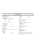
Page 6: ...voltage Short Circuit METERING Voltmeter Range Accuracy 0 to 20V 7 F S Ammeter Range Accuracy 0 to 20A 7 F S AC Input 115 230 VAC 10 50 60Hz POWER CONSUMPTION 400 W TEMPERATURE RANGE HUMIDITY Operatio...

Page 7: ...eed 2 amperes 10 Line Cord 11 Fuse 12 Fan 1 POWER Switch Turns power supply on and off Power on indicated by pilot lamp above switch 2 Power ON light Lights when power is turned on 3 OVERLOAD Indicato...

Page 8: ...8 CONTROLS AND INDICATORS Figure 1 Front Panel Controls and Indicators Model 1686A Figure 2 Rear Panel...

Page 9: ...Observe all TEST INSTRUMENT SAFETY precautions listed in the front of this manual EQUIPMENT PROTECTION PRECAUTIONS CAUTION The following precautions will help avoid damage to the power supply 1 Avoid...

Page 10: ...nugly to assure low resistance 2 Connect the red OUTPUT terminal of the power supply to the positive polarity input of the equipment being powered 3 Connect the black OUTPUT terminal of the power supp...

Page 11: ...provide a variable 6 to 28 volts output The maximum output current will remain at 12 amps See Fig 4 for the connection scheme The voltage is controlled by both VOLTAGE controls and is equal to the sum...

Page 12: ...12 OPERATING INSTRUCTIONS Figure 4 Connecting Two Power Supplies in Series for a 6 to 28 Volt Output...

Page 13: ...13 OPERATING INSTRUCTIONS Figure 5 Connecting Two Power Supplies in Parallel for 3 to 14 Volt Output at Double Amperage...

Page 14: ...e bottom of the chassis To convert to a different line voltage perform the following procedure 1 Make sure the power cord is unplugged 2 Turn the unit over bottom up and reset the LINE VOLTAGE SELECT...

Page 15: ...14 50 0 10 volts on the multimeter 4 Set the power supply front panel VOLTAGE control for a reading of 14 00 0 10 volts on the multimeter 5 Adjust Trimmer VR4 so that the meter pointer on the V meter...

Page 16: ...tive load for a reading of 15 amps on the unit s A meter scale 8 Adjustable Trimmer VR2 clockwise unit the output voltage read on the multimeter drops by 0 05 to 0 20 V INSTRUMENT REPAIR SERVICE Becau...

Page 17: ...ccount must include payment in the form of a money order or credit card For the most current repair charges please visit www bkprecision com and click on service repair Return all merchandise to B K P...

Page 18: ...nstrument via our website www bkprecision com Exclusions This warranty does not apply in the event of misuse or abuse of the product or as a result of unauthorized alterations or repairs The warranty...

Page 19: ...et is removed for servicing a serious shock hazard exists if the chassis is touched Not only does this present a dangerous shock hazard but damage to test instruments or the equipment under test may r...

Page 20: ...20 B K Precision Corporation 22820 Savi Ranch Parkway Yorba Linda California 92887 www bkprecision com 2014 B K Precision Corporation 481 370 9 001 Printed in China V043014...

Reviews: