background image

""' 

FUNCTIONS 

CLOCK 

I

(1<1JO 

Hz) 

COUNTING 

CONTROL 

MEMORY 

UPDATE 

RESET 

(1) 

TIME  BASE 

UPDATE 

OVER-

RANGE 

SIGNAL 

WAVE  FORMS 

I  I 

I  I 

10 mSEC 

'"I,. 

--TIME  BASE 

� 

 2 50 mSEC 

MAX. 

I

t. 

0.2 

µ 

n--150 

µ5  TYP.

TYP. 

ti 

0.2 IJS

1

r

250mSEC

TYP.  !

TYP. 

I  ''  I 

µSl 

rr-

BµS 

TYF!

TYP. 

I....,. 

/

:n 

-------

I  I 

Fig. 16. 

Timing diagram. 

TEST 

POINTS 

REMARKS 

GENERAL: 

(1) 

ALL  CONTROL 

OR  2  SIGNALS  Ac'TIVATE  AT  LOGIC 

OR  3 

"l"  LEVELi  (2)  ALL  SIGNALS 

ARE  AT  TTL  LEVELS.  (3) 

.100  Hz

CLOCK  IS  USED  AS  AN  EXAMPLE. 

n_ 

RESET  NO.  2  HAS  THE 

COMPLEMENTARY  WAVEFORM 

� 

THIS  PULSE  C{>ULD  OCCUR 

----

AT  ANY  TIME  DURING  THE 

COUNTING  PERIOD. 

Summary of Contents for 1801

Page 1: ...mazmr1801 6 DIGIT AUTORANGING FREQUENCY COUNTER ...

Page 2: ... the counter as listed in the SPECIFICA TIONS section or damage to the instrument may occur Even when measurements are made at low voltage points be careful to avoid touching any high voltage point Remember that ac line voltage is usually present on some power input circuits such as on off switch fuses power transformer etc any time the equipment is connected to an ac outlet even if it is turned o...

Page 3: ...INSTRUCTION MANUAL FOR B K PRECISION MODEL 1801 6 DIGIT AUTORANGING FREQUENCY COUNTER 6470 West Cortland Street Chicago Illinois 60635 ...

Page 4: ...rols and Features 7 B Interpretation ofDisplay Readings 7 C Operation 9 D Applications 10 E Modifications 11 THEORY OF OPERATION 12 RECALIBRATION AND MAINTENANCE 12 BLOCK DIAGRAM 13 TIMING DIAGRAM 14 APPENDIX Damping Resistor Calculation 15 WARRANTY INSTRUCTIONS 16 WARRANTY Cov 3 3 ...

Page 5: ... with DC to AC power inverter SPECIFICATIONS 1 FREQUENCY CHARACTERISTICS Range 20Hz to 40 MHz guaranteed 10 Hz to over 60 MHz typical Function switch selects kHz or AUTO display reading Gate Time Auto 10 mSEC or 100 mSEC MHz reading or 1 SEC kHz reading chosen automatically Gate Time Manual 1 SEC kHz reading 1 Hz resolu tion Accuracy time base accuracy 1 count Resolution Display 1 Hz Frequency of ...

Page 6: ... 0 ctS I I 200 Lu c 150 X I E 50 I 2 3 4 56 7891 2 3 0 100 4 56 7891 l 500 IK 2 3 4 56 7891 2 IM FREQUENCY Hz Fig 1 Maximum input protection derating curve 3 4 56 7891 I _ 5M IOM 2 3 4 56 7891 40M __ IOO M ...

Page 7: ... l l l 1 4 f I ________ ______ _ f 401 I I 1 111111 I 1 111111 I I 11 111 11 I I 1111111 I I I Ill 0 I I t I 11 GUARANTEED 30 1 I 11111111 I JI 111111 I 11lfllll I 11illlll I 11111111 t _ _ 20 I I I I I 11 I T l f 1 11111 Yr mt 1 rtrffftt H IO I I I I I I I I I I I I I I I I I I I I I I I I I I I I I I I I I I _ __ __ __ __ __ I I I I I I I I I I I I I I I Hz 01 I I 1111111 I jfl 11 111 I I 111111...

Page 8: ...y is beyond the selected display range 7 STAND Can be pushed against chassis so that the unit will sit on its feet or can be pulled out to tilt the unit at a convenient viewing angle 18D1 FREQUENCY COUNTER Fig 3 Controls and features B INTERPRETATION OF DISPLAY READINGS For purposes of identification the six display digits of the counter will be identified numerically as shown in the display drawi...

Page 9: ...f the frequency 1 654 321 Hz would then appear as shown in Fig 9 1 Sec OFF e ALJTO KHz I I_ _I I J I LI _I I _I I_ 0 OVER MHz Fig 9 Note that the MHz lamp is now lit and that the least significant digit I is no longer being displayed at the right end of the display and the most significant digit 1 has been added at the left end of the display When the most significant digit is displayed the OVER l...

Page 10: ...blocking capacitor is required in the cases where the circuit DC bias might be affected by the Transmitter Signal Tap termination resistor To avoid the requirement for use of a terminated transmission line a com pensated high impedance I0 I probe can be used instead Signal cables available from Dynascan are a I0 I and 1 I compensated counter probe PR 25 or b I0 I and 1 I osciJloscope probe PR 24 T...

Page 11: ...ip EPEAK l 4y PR where Pis power output in watts R is load resistance in ohms Using a 4 watt output into 50 ohms EPEAK l 4y 4x50 20 volts If we consider that this value can almost double with 100 percent modulation and can be multi plied several times again by severe load mis 50 pf Air Variable Chicago Illinois 60635 c A SO ohm termination resistor is required at the counter input if a SO ohm coax...

Page 12: ...reater than the allowable power line frequency devia tion The following are provided as safety guidelines in the event that line frequency measurements are performed AC Outlet a If the instrument is operated from a grounded outlet which is highly recom mended only the center conductor of the input cable should be connected to the power line Otherwise a short circuit might result If a reading is no...

Page 13: ...d state the demultiplexer selects a decade longer period 100 mSEC if the underrange de tector detects zero in MSD IC21 This cycle will repeat until the MSD begins to count or the demultiplexer reaches the 1 SEC time base If the incoming signal is increased in frequency and the instrument is overranged the binary counter is reset and a new auto ranging sequence is initiated Since the gates of IC27 ...

Page 14: ... a 1 TIME BASE GENERATOR I l I ____ I I ___J I I I ___ I CONTROL PULSE GENERATOR lfl I I I I I ITRANSFER r I I I I MEMORY BINARY COUNTER 11 I MULTIPLEXER DRIVER I I I I I I CONTROL CIRCUIT I I I I I 2 TIME BASE _I CONTROL I f MULTIPLEXER I 6 POWER SUPPLY r I r I t DECIMAL I I I I _ ___ ___ J I I I I I I I I POWER I I SUPPLY I SW TCH I I I I I I I ___ _ _ _ UNDERRANGE I DETECTOR I L_I ______J 1 POI...

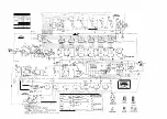
Page 15: ... µ5 TYP TYP I I ti 0 2 IJS 1 r 250mSEC l TYP TYP I i I I I I I 5 µSl rr BµS TYF TYP I I I I I I I n I I I I I I I Fig 16 Timing diagram TEST POINTS REMARKS GENERAL 1 ALL CONTROL 1 OR 2 SIGNALS Ac TIVATE AT LOGIC I OR 3 l LEVELi 2 ALL SIGNALS ARE AT TTL LEVELS 3 100 Hz CLOCK IS USED AS AN EXAMPLE I I n_ I I I I RESET NO 2 HAS THE I COMPLEMENTARY WAVEFORM I I 6 I 7 THIS PULSE C ULD OCCUR AT ANY TIME...

Page 16: ...plitude and because the frequency is usually unknown before the measurement only an approximate value for Rd can be obtained by guessing the source frequency In order to maintain a minimum voltage of 30 mV RMS at the divider output value of Rd can be determined by the following relations I Xe 2 1r 1 c capacitor impedance at frequency f1 2 C Ci Cc 3 R Vs Vo X d Vo c where Ci 20 pF typical Cc 87 pF ...

Page 17: ...uipment always connect an isolation transformer between the ac outlet and the equipment under test The B t K Precision Model TR 110 Isola tion Transformer or Model 1653 or 1655 AC Power Supply is suitable for most applications To be on the safe side treat all two wire ac powered equipment as hot chassis unless you are sure it has an iso lated chassis or an earth ground chassis 7 Servicing of this ...

Page 18: ...tCf i t SEGMIEl TS 0 All OIGITS A CO rECTED 1 1 000 TA lf TANfAl UM 111 so MOST S GN f W AIIIT 1 6 N 1 000 000 Ill F METAL FLlro LS O Lt AST Sl HFIGIINT 01 T 4 FOIL I tt CASE GROJ 0 7Rl88Hl w S rutRA t RECTLl CONr l OTQ TA ll NSHJRMfH 8 r EJ lial j 5 SrWWl i lTAllCS IN SQUARES AH TYPICAL VALuES Iii IIO i S Ml c SuHf l CLOCK IOOHz OVER R NGE SIGIIIAl _n____c_ __ ___ _ T0 3 PKG Q69JTTOIIVEW rET D S ...

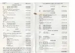
Page 19: ...gements have been made or remittance accompanies order Advance remittance must cover postage or express charges Specify serial number when ordering replacement parts B K DYNASCAN CORPORATION 1801 W Belle Plaine Ave Chicago Illinois 60613 SCHEMATIC SYMBOL B K PRECISION MODEL 1801 PARTS LIST 488 145 9 002C B K DESCRIPTION PART NUMBER RESISTORS R29 10k 1 1 I 2W P F Metal Film 011 020 9 001 R30 4 99k ...

Reviews: