Selftest of programmer
•
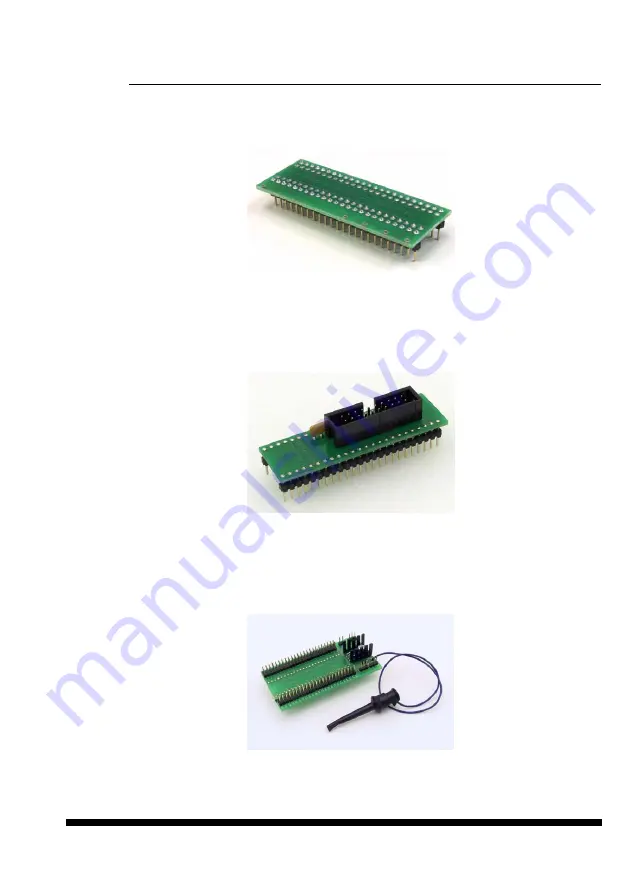
Insert
48 pins diagnostic POD - type I
into ZIF socket of the programmer.
48 pins
diagnostic POD - type I
must be inserted as 48 pins device.
•
Run selftest of programmer in PG4UW (Programmer / Selftest plus).
Selftest of ISP connector
•
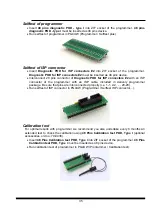
Insert
Diagnostic POD for ISP connectors #2
into ZIF socket of the programmer.
Diagnostic POD for ISP connectors #2
must be inserted as 48 pins device.
•
Interconnect 20 pins connector of
Diagnostic POD for ISP connectors #2
with an ISP
connector of the programmer with an ISP cable, included in delivery programmer
package. Be sure that pins are interconnected properly (i.e. 1-1, 2-2, ..., 20-20).
•
Run selftest of ISP connector in PG4UW (Programmer / Selftest ISP connector…).
Calibration test
For optimal results with programmer we recommend you also undertake every 6 months an
extended test to check the calibration using
48 Pins Calibration test POD, Type I
(optional
accessories, ord.no. 70-0438).
•
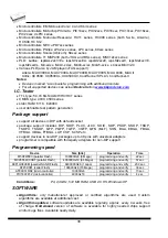
Insert
48 Pins Calibration test POD, Type I
into ZIF socket of the programmer.
48 Pins
Calibration test POD, Type I
must be inserted as 48 pins device.
•
Run calibration test of programmer in PG4UW (Programmer / Calibration test).
35
Summary of Contents for 844USB
Page 7: ...Introduction 7 ...
Page 12: ...Quick Start 12 ...
Page 15: ...Detailed description 15 ...
Page 16: ...859 16 ...
Page 28: ...866B 28 ...
Page 41: ...844USB 41 ...
Page 50: ...848A 50 ...
Page 56: ...Setup 56 ...
Page 67: ...Pg4uw 67 ...
Page 117: ...Pg4uwMC 117 ...
Page 127: ...Common notes 127 ...
Page 134: ...Troubleshooting and warranty 134 ...


