2.
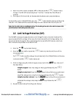
Select
o
ne
o
f
t
he
options
av
ailable,
OFF o
r
O
N
and
pre
ss t
he
butto
n to s
ave
changes.
The
VFD
will
momentarily
s
how
“
Trac
S
ucc”
t
o
s
how
that
T
rack
M
ode
is
enabled.
3.
The
ou
tput
of
CH1
a
nd
C
H2
ca
n
be
a
djusted
s
imultaneously
a
s
explained
a
bove.
To
c
heck
i
f
t
he
uni
t i
s
in
TRACK
MO
DE,
p
ress
the
butto
n and
the
display
will
s
ho
w
the
indicato
r
“trA”
und
ernea
th
the
measured
voltage
f
o
r
each
channel
wh
en
the
o
utput
i
s
off.
Note: Set the ratio before enabling tracking.
The tracking is based on the ratio between CH1
and CH2 when the tracking mode is active.
3.2
Limit Voltage Protection (LVP)
Th
e 9
129B
M
odel
power
s
upply
pr
ovides
a
Limit
V
oltage
P
rotection
functio
n t
o
pr
otect
t
he
power
s
upply
wh
e
n th
e
v
oltage
a
t
the
o
utpu
t
terminal
e
xceeds
t
he
LVP
v
oltage
s
etting
or
to
prevent
ac
cidental
changes
t
o
t
he
o
utpu
t s
ettings
that
exceeds
th
e
DU
T
(device
under
t
est)
limit
.
Follow
the
s
teps
b
elow
t
o
s
e
t
the
LVP
limi
t.
1.
Press
the
key
to
s
elect
c
hannel.
2.
Press
the
key
and
the
n
pre
ss
the
button
to
e
nter
the
L
VP
m
en
u of
the
channel
s
elected
.
Th
e
button
and
t
he
v
oltage
c
hanne
l s
elected
(
in
the
V
FD)
will
blink
unt
il a v
alue
is
e
ntered
a
n
d th
e
button
i
s p
ressed.
3.
Ente
r a v
oltage
using
the
num
eric
k
eypad,
r
otary
kno
b o
r
t
he
keys
. Us
e
one
of
the
s
teps
b
elow.
Using the keypad:
Enter
the
v
oltage
on t
he
k
eypa
d f
ollowe
d
by
th
e
button.
Using the rotary knob:
Press
the
keys
to
m
ove
the c
ursor
positio
n a
nd
adjus
t t
he
voltage
v
alue
using
the
r
otary
k
nob
followed
b
y
the
button.
Using the Up/Down arrows:
Press
the
keys
to
m
ove
th
e
c
ursor
po
sitio
n
a
nd
adjus
t th
e
voltage
v
alue
us
ing
the
keys
followed
b
y
the
button.
4.
Repeat
t
he
a
bove
s
teps
f
or
s
etting
e
ach
c
hannel.
www.
GlobalTestSupply
.com
Find Quality Products Online at:
sales@GlobalTestSupply.com


