22
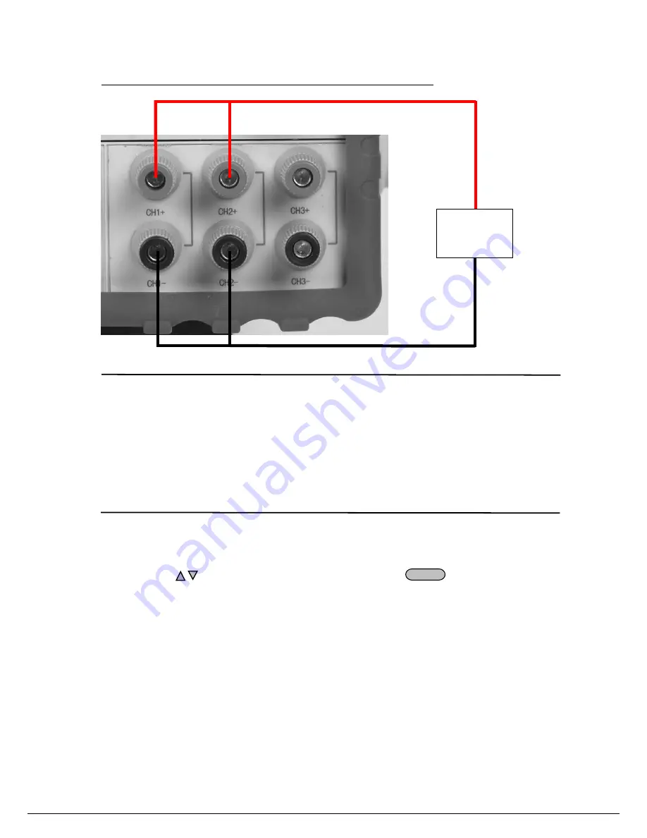
Connection diagram example: Channels 1 and 2 connected in parallel
Note: When configuring for series or parallel operation, the user must wire
the terminals to match the configuration. The power supply does not
automatically connect the appropriate terminals internally based on the
configuration selected.
MaxVolt Set (LVP)
The max voltage you set should be within the range of 0V to the maximum rated voltage. You can edit this
value using the
keys or via numerical key pad followed by
Enter
. The default setting is the
maximum rated voltage for each channel.
Out Time Set
This parameter sets the output timer for each channel. The range is 1~999999 seconds. If you enable this
function, and the output state of all channels is on, the timer will start counting down immediately. Once the
timer expires (count down from set value to zero) the output of the assigned channel will turn off. To disable
the timer, set the output time to zero.( 0 seconds). Default setting is 0 Seconds.
Load
+


