8
•
Software installation disk
2
.
Connect the power cord and turn on the power supply
When you turn on the power supply, the front-panel display will light up briefly while the power supply
performs its power-on self-test. All the VFD annunciators will turn on at once. Check for any missing display
segments. In the event that there is no response when you turn on the power supply, refer to section 5 of this
chapter for additional information.
3. System Checkout
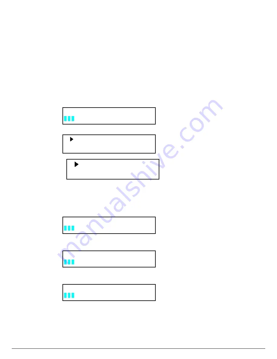
At power up, the instrument will automatically perform a self test routine. During this time, the following
should be displayed:
System Test, Please wait!
followed by
0.000V 0.000V 0.000V
<OFF> <OFF> <OFF>
Or:
Note: The first row is the output voltage for channels 1 – 3. The second row will display the on/off state or the
output current of each channel.
In case the self test routine is not successful, you may see one of the following:
If the EEPROM is damaged, the VFD will display the following:
EEPROM Error
I
f the last operation data which should be stored in the EEPROM was lost you should see
Data Check Error
If the latest data about off-time in EEPROM was lost, the VFD will display
Load Off Time Fail
If the calibration data stored in the EEPROM was lost, the VFD will display
10.000V 11.000V 3.000V
2.000A 3.000A 3.000A


