Ventless Hood System
Replacement Parts
21
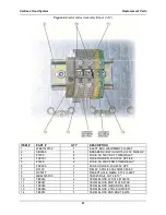
Figure 6.
Electrical Box Assembly (Sheet 2 of 2)
ITEM #
PART #
QTY
DESCRIPTION
1
WB37140100
1
ELECT.BOX WELDMENT FH-28CT
2
CB0066
4
BREAKER,CIR.W/LUGS 15A 120V 50/60HZ
3
F0100
2
FUSE, 1A 300V SC-1 TIME DELAY
4
FH0001
2
FUSE HOLDER, 15A 300V HPF-EE
5
F0336
2
FUSE, 5A 250V FNM5 TIME DELAY
6
FH0006
2
FUSE HOLDER, 30A 600V HPF
7
R0129
1
RELAY, 3POLE 60A 208/240 50/60
8
RC0017
4
RECEPTACLE, NEMA 5-15 FH-28CT
9
MB44023700
1
TB0045 RAIL CUT 2.813"
10
TB0046
2
TERM BLOCK, WDU10 #102030
11
TB0047
1
TERM BLOCK END PLATE WAP
12
TB0048
1
TERM BLOCK GROUND BLOCK
13
TB0049
1
TERM BLOCK 2 POLE JUMPER
14
TB0051
1
TERM BLOCK END BRKT EW35
Summary of Contents for FH-28CT COUNTERTOP
Page 1: ...CS TM 041 01 Revised 04 17 13 Ventless Hood System MODEL FH 28CT COUNTERTOP Service Manual ...
Page 11: ...Ventless Hood System Installation 9 Figure 1 ...
Page 12: ...Ventless Hood System Installation 10 Figure 2 ...
Page 13: ...Ventless Hood System Installation 11 Figure 3 Right Side Pull Station Mounting ...
Page 14: ...Ventless Hood System Installation 12 Figure 4 Left Side Pull Station Mounting ...
Page 15: ...Ventless Hood System Installation 13 Figure 5 Complete Pull Station Mounting ...
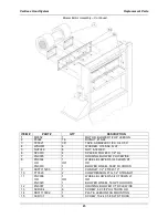
Page 24: ...Ventless Hood System Replacement Parts 22 Figure 7 Blower Motor Assembly ...
Page 26: ...Ventless Hood System Replacement Parts 24 Figure 8 Right Side Cabinet Assembly ...
Page 28: ...Ventless Hood System Wiring Diagrams 26 Wiring Diagrams ...

