Page 3
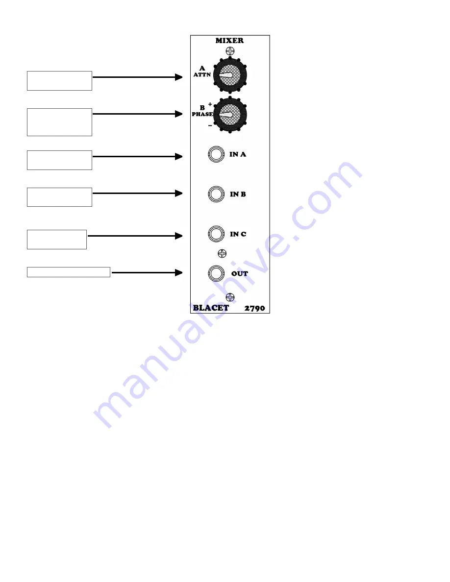
Channel A
Attenuator
Channel A
Input
Channel B
Input
Channel C
Input
Channel B
Attenuator &
Phase Control
Mixer Output
Operation Tips
Use this mixer to spot mix CVs and audio
in your patches.
It may be helpful to assign the softest sound
or smallest CV to the “C” input as the other
larger inputs can be attenuated by the pots.
Note that the “C” level can also be
adjusted from 50 to 100% by the on board
trimmer if “full on” is not the best setting
for your typical use.
One typical application is to mix several
CV sources and apply them to a VCO or
filter frequency input.
For example, a mixture of noise and LFO
triangle sent to the VCO octave input can
be adjusted for an octave jump with some
uncertainty.
Power Input Connector JPWR:
This PCB connector requires a source of reg15Vdc and -15Vdc power to
run the module. Use a Blacet PS500 supply or the equivalent.
Connections to this connector should be made only when the power supply is OFF and the connector must be
positioned correctly on the pins.
As using the wrong supply can cause damage to the unit, please contact us if you
have any questions! Do not attempt to use “wall warts” to power the module.
Calibration:
Both PCBs have a “Null” trimmer for the “B” Channel (RT1). Adjust this with the B channel front
panel control at center detent position for minimum output, using an audio signal input (“IN” Splitter or “IN B
Mixer).
The Mixer also has a “C Level” trimmer (RT2) which can be adjusted from 50% to 100%. The center position is 75%.


