background image

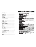
Getting the most out of your tool.

Please take time to read this manual and pay particular attention to the safety rules we’ve provided for
your protection. Don’t forget to send in your owner’s registration card. If you have any questions
about your tool please call:

1-800-9-BD TOOL

(1-800-923-8665) 

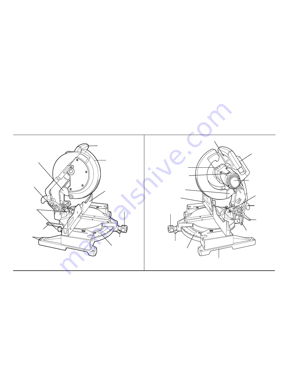
REAR LOWER GUARD

OPERATING HANDLE

GUARD

RIGHT SIDE
FENCE

MITER LATCH

MITER SCALE

LOCK DOWN PIN

BLADE WRENCH

MITER CLAMP KNOB

BENCH
MOUNTING
HOLES

REAR LOWER GUARD

BRUSH INSPECTION CAP

LEFT SIDE OF FENCE

MITER CLAMP
KNOB

MITER LATCH

MITER SCALE

HAND INDENTATION

DUST SPOUT

MOTOR HOUSING

CARRYING HANDLE

SPINDLE LOCK BUTTON

LEFT SIDE FENCE
CLAMPING
KNOBS

TRIGGER SWITCH

BEVEL CLAMP
KNOB

BEVEL SCALE

BEVEL STOP

Summary of Contents for 3680 12"

Page 1: ...3680 12 Compound Miter Saw Instruction Manual TM ...

Page 2: ...l please call 1 800 9 BD TOOL 1 800 923 8665 REAR LOWER GUARD OPERATING HANDLE GUARD RIGHT SIDE FENCE MITER LATCH MITER SCALE LOCK DOWN PIN BLADE WRENCH MITER CLAMP KNOB BENCH MOUNTING HOLES REAR LOWER GUARD BRUSH INSPECTION CAP LEFT SIDE OF FENCE MITER CLAMP KNOB MITER LATCH MITER SCALE HAND INDENTATION DUST SPOUT MOTOR HOUSING CARRYING HANDLE SPINDLE LOCK BUTTON LEFT SIDE FENCE CLAMPING KNOBS TR...

Page 3: ... accessories such as blades bits cutters etc 15 R RE ED DU UC CE E T TH HE E R RI IS SK K O OF F U UN NI IN NT TE EN NT TI IO ON NA AL L S ST TA AR RT TI IN NG G Make sure switch is in OFF position before plugging in 16 U US SE E R RE EC CO OM MM ME EN ND DE ED D A AC CC CE ES SS SO OR RI IE ES S Consult the instruction manual for recommended acces sories The use of improper accessories may cause ...

Page 4: ...R RN NI IN NG GS S M MA AY Y R RE ES SU UL LT T I IN N P PE ER RS SO ON NA AL L I IN NJ JU UR RY Y A AN ND D S SE ER RI IO OU US S D DA AM MA AG GE E T TO O T TH HE E S SA AW W 2 D DO O Protect electric supply line with at least a 15 ampere time delay fuse or a circuit breaker 3 D DO O Make certain the blade rotates in the correct direction and that the teeth at the bottom of the blade are pointin...

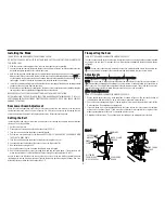
Page 5: ...he convenient carrying handle as shown in Figure 1 Place the saw on a smooth flat surface such as a workbench or strong table Examine Figures on inside front cover of this manual to become familiar with the saw and its various parts The following section on adjust ments will refer to these terms and you must know what the parts are Press down lightly on the operating handle and pull out the lock d...

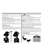
Page 6: ...he guard bracket screw shown in Figure 3 until the guard bracket can be raised enough to permit access to the blade screw 3 Hold the lower guard up and depress the spindle lock button with one hand and use the supplied blade wrench in the other hand to loosen clockwise the left hand threaded blade screw N NO OT TE E To use the spindle lock depress the button as shown and rotate the spindle by hand...

Page 7: ... the bevel arm resting against the left side bevel stop screw 3 Hold the screw stationary while you firmly tighten the lock nut DO NOT ADUST THE BEVEL POINTER To achieve 3 right bevel or 48 left bevel the top screws must be adjusted to allow the bevel arm to move as necessary Re adjust the bevel stops when the cuts are finished F Fe en nc ce e A Ad dj ju us st tm me en nt t TURN OFF TOOL AND DISCO...

Page 8: ...miter clamp knob Make the cut as described above Bevel Cuts A bevel cut is a crosscut made with the saw blade at a bevel to the wood In order to set the bevel loosen the bevel clamp knob and move the saw to the left as desired It is necessary to move the left side of the fence to allow clearance as you did under Bevel Stop Adjustment Once the desired bevel angle has been set tighten the bevel clam...

Page 9: ...lable from your dealer at extra cost Support long work pieces using any convenient means such as sawhorses or similar devices to keep the ends from dropping Cutting picture frames shadow boxes and other four sided projects To best understand how to make the items listed here we suggest that you try a few simple projects using scrap wood until you develop a FEEL for your saw Your saw is the perfect...

Page 10: ...4 RIGHT MITER 1 4 VERNIER MARK ALIGNS WITH CLOSEST WHOLE DEGREE MARK ON MITER SCALE 24 1 4 RIGHT MITER N NO OT TE E If the cutting angle varies from cut to cut check that the bevel clamp knob and the miter lock knob are securely tightened These knobs must be tightened after making any changes in bevel or miter The chart shown on page 10 will assist you in selecting the proper bevel and miter setti...

Page 11: ... vertically against the fence Position molding as shown in Figure 20 All cuts made with the back of the molding against the fence I IN NS SI ID DE E C CO OR RN NE ER R Left side 1 Position molding with bottom of molding against the table of the saw 2 Miter left 45 3 Save left side of cut Right side 1 Position molding with top of the molding resting on the table of the saw 2 Miter left 45 3 Save le...

Page 12: ...urfaces on a given piece of crown molding are at angles that when added together equal exactly 90 Most but not all crown molding has a top rear angle the section that fits flat against the ceiling of 52 and a bottom rear angle the part that fits flat against the wall of 38 Your miter saw has special preset miter latch points at 31 62 left and right for cutting crown molding at the proper angle The...

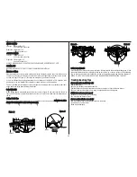
Page 13: ... ic c P Pi ip pe e Plastic pipe can be easily cut with your saw It should be cut just like wood and C CL LA AM MP PE ED D O OR R H HE EL LD D F FI IR RM ML LY Y T TO O T TH HE E F FE EN NC CE E T TO O K KE EE EP P I IT T F FR RO OM M R RO OL LL LI IN NG G F Fi ig gu ur re e 2 27 7 FENCE W WR RO ON NG G BLADE F Fi ig gu ur re e 2 26 6 R RI IG GH HT T BLADE FENCE C Cu ut tt ti in ng g L La ar rg ge ...

Page 14: ...PL LI IC CA AT TI IO ON N B BL LA AD DE E N NO O O OF F T TE EE ET TH H T TY YP PE E O OF F C CU UT T Fine Trim Molding Precision 60 100 Very smooth Ground Carbide splinter free Trim Framing Pressure Combination 32 60 Smooth fast cut Treated Decking Multi Purpose Aluminum Non Ferrous 60 80 ____ Metal Cutting ACCESSORIES MAINTENANCE 1 All bearings are sealed ball bearings They are lubricated for li...

Page 15: ...ter first year of ownership Please return the complete unit transportation prepaid to any B D factory owned or B D authorized service center location list pro vided with tool or see Yellow Pages under Tools Electric E Ev ve er ry y B B D D t to oo ol l i is s o of f t th he e h hi ig gh he es st t q qu ua al li it ty y I If f y yo ou u w wi is sh h t to o c co on nt ta ac ct t u us s r re eg ga ar...

Page 16: ...Black Decker U S Inc 701 East Joppa Road Towson Maryland 21286 Printed in U S A JAN94 CD 1 Form No 159185 Copyright 1994 ...

Reviews: