
ENGLISH
ENGLISH
7
9
10
8
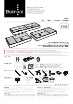
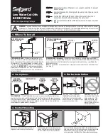
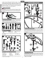
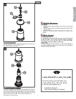
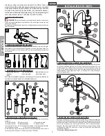
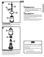
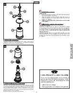
7 CONTROL BODY INSTALLATION
Place a bead of plumber’s putty in the groove along the bottom outer edge of Plastic
Gasket (
7A
). Place Plastic Gasket (
7A
) against the bottom of Control Body (
7B
). From
above sink, insert Threaded Shank (
7C
) and Tubing (
7D
) through side hole of sink.
From underneath sink, place Washer (
7E
) and Locknut (
7F
) through Hose (
7G
). Secure Control
Body (
7B
) by threading Locknut (
7F
) onto Threaded Shank (
7C
). Tighten loosely, make sure
Handle (
7H
) swings equally in both directions. Tighten Control Body (
7B
) firmly to sink.
Caution: Do not over tighten!
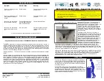
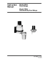
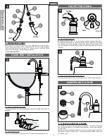
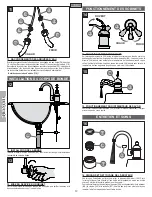
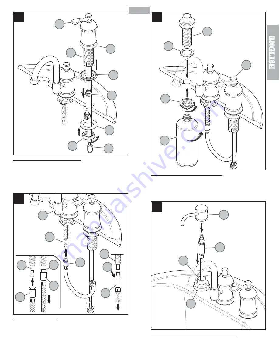
8 HOSE ATTACHMENT
Push Quick Connect Housing (
8A
), firmly upward onto the Receiving Tube (
8B
) located
on the bottom of the Spout Body (
8C
), until unable to push any further. Pull down on the
Quick Connect Housing (
8A
). If the housing and the Inner Collet (
8D
) separate slightly
but do not pull off, the Receiving Tube (8B) the connection is secure.
To remove Hose (
8D
), push up on Quick Connect Housing (
8A
), holding Inner Collet
(
8D
) in place, pull downward on Quick Connect Housing (
8A
) until Receiving Tube
(
8B
) is free.
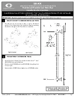
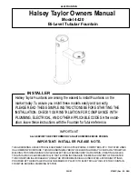
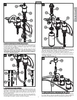
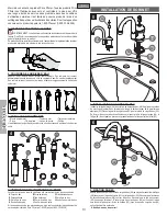
9 SOAP DISPENSER INSTALLATION
Insert Soap Dispenser Shank (
9A
) through Foam Gasket (
9B
) and into the sink holes.
[Both Control Body (
9C
) and Dispenser Shank (
9A
) can be placed in either end hole].
From underneath sink, secure Soap Dispenser Shank (
9A
) by screwing Plastic Locknut
(
9D
). Thread Bottle (
9E
) to Soap Dispenser Shank (
9A
). Hand tighten.
Caution: do not over tighten!
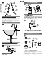
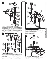
10 SOAP DISPENSER HEAD INSTALLATION
Pour in liquid soap (
not included
) into Shank Orifice (
10A
). Insert Pump Mechanism
(
10B
) into Soap Dispenser Shank (
10C
). Install Dispenser Head (
10D
) by pushing firmly
onto Pump Mechanism (
10B
).
3
7A
7B
7E
7G
7F
7C
7H
7D
9A
9B
9D
E
9C
10B
10D
10A
10C
8A
8A
8D
8D
8A
8B
8A
8B
8B
8C