

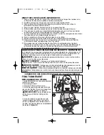


IMPORTANT SAFETY INSTRUCTIONS
1. Do not load with more than 400 lbs. (181kg). Do not leave heavy loads on work surface
for extended periods of time.
2. Do not apply an unbalanced load which could cause the workbench to tip over.
3. Do not use the work center as a stepladder or standing platform. Do not use the lower
platform as a step.
4. Do not store workbench outdoors or in a damp location.
5. Avoid applying excessive force when clamping with the supplied clamps.
6. Be sure that the legs are fully open and the center support is in position and locked
before use.
7. When using a power tool with the workbench, follow the safety instructions in the tool’s
instruction manual.
8. Do not mount or clamp power tools to any surface.
9. Always wear safety glasses when operating power tools.
10. Cutting or drilling into work surface may weaken supports, damaging tool or workbench.
11. Caution required when using high temperature tools (heat guns, torch, solder
iron, etc.). May damage work surface and reduce clamping capability.
12. Do not store flammable liquids on the workbench.
SAFETY GUIDELINES - DEFINITIONS
It is important for you to read and understand this manual. The information it contains
relates to protecting YOUR SAFETY and PREVENTING PROBLEMS. The symbols
below are used to help you recognize this information.
DANGER:
Indicates an imminently hazardous situation which, if not avoided, will
result in death or serious injury.
WARNING:
Indicates a potentially hazardous situation which, if not avoided, could
result in death or serious injury.
CAUTION:
Indicates a potentially hazardous situation which, if not avoided, may
result in minor or moderate injury.
CAUTION:
Used without the safety alert symbol indicates a potentially hazardous
situation which, if not avoided, may result in property damage.
SAVE THESE INSTRUCTIONS FOR FUTURE USE
OPERATION
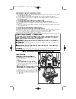
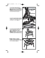
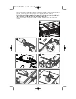
OPENING THE WORKBENCH
The BDWM1000 is packaged completely
folded in the carton.
To open:
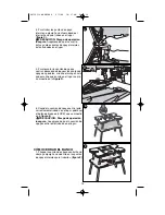
1. Place the workbench flat on the floor.
2. Grasp the openings on both sides of the
table top and pull out on the release latches
as shown in
figure A
.
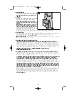
CAUTION:
Do not pull the legs out when
the workbench is in a closed position.
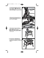
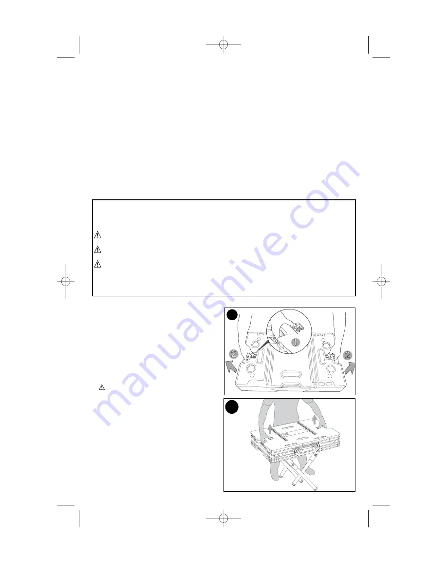
3. With the release latches pulled in, lift the
table top. The four legs will drop down and
lock into place and the side supports will lift
up. (
figure B
)
1
A
B
2
90539119 BDWM1000 6/5/08 10:17 AM Page 2


