


8
ENGLISH
(Original instructions)
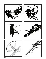
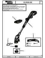
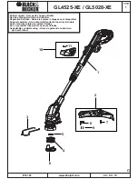
Assembly
Warning! Before assembly, make sure that the tool is
switched off and unplugged.
Remove the screw from the guard.
Keeping the guard (6) square to the strimmer head (8)
slide it into place until the retaining tab clicks into place
(Ensure that the guide rails (10) on the guard (6) are
correctly aligned with the guide rails (11) on the strimmer
Secure the guard (6) with the screw (12).
Warning! Never use the tool unless the guard is properly
Slide the second handle (5) on to the main handle (2) in
an upwards direction.
Secure the second handle in place with the screw (13)
provided.
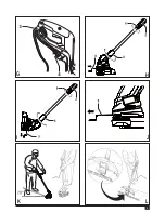
Press in and hold both of the buttons (14) on the side of
the handle.
Slide the second handle (5) in place over the buttons (14).
Warning! Ensure that the teeth on the button are correctly
aligned in slots in the handle and that the handle is secure.
E) (GL5530-XE only)
The second handle (5) can be adjusted to provide optimum
balance and comfort.
Press in the button (15) on the left side od the handle.
Rotate the second handle (5) into the required position.
Release the button (15).
Warning! Ensure that the teeth on the button are correctly
aligned in slots in the handle and that the handle is secure.
This tool has a telescopic mechanism, allowing you to set it to
a comfortable height. There are multiple height settings.
To adjust the height setting, proceed as follows:
Disconnect the tool from the supply.
Loosen the adjustment collar (16) by turning it clockwise.
Gently pull the tube (17) in or out of the handle (2) to the
desired height.
Tighten the adjustment collar (16) by turning anti-
clockwise.
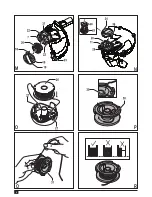
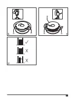
Releasing the cutting line
In transit, the cutting line is taped to the spool housing.
Remove the tape holding the cutting line to the spool
housing (7).
Connect the female plug of a suitable extension cable to
the power inlet (4).
Loop the cable through the cable restraint (3).
Insert the mains plug into a mains outlet.
For wired in cable units: Make sure the cable is looped
through the cable restraint prior to connecting the plug to the
mains outlet.
Warning! The extension cable must be suitable for outdoor
use.
Use
Warning! Let the tool work at its own pace. Do not overload.
I & J)
edging mode to trim overhanging grass along lawn edges and
For trimming, the trimmer head should be in the position
Disconnect the tool from the supply.
Loosen the adjustment collar (6) by turning it clockwise.
Whilst holding the handle (2), rotate the head (8)
clockwise.
Tighten the collar (6) by turning it anti-clockwise.
Slide the edge guide (9) into the motor housing.
Note: Note: The head will only rotate in one direction.
For edging, the trimmer head should be in the position shown
Disconnect the tool from the supply.
Loosen the adjustment collar (6) by turning it clockwise.
Whilst holding the handle (2), rotate the head (8)
anti-clockwise.
Tighten the collar (6) by turning it anti-clockwise.
Slide the edge guide out of the motor housing. Ensure that
the edging guide (9) is fully extended, an audible click will
be heard.
Note: The head will only rotate in one direction.
Switching on and off
To switch the tool on, squeeze the trigger lever (1).
To switch the tool off, release the trigger lever.
Warning! Never attempt to lock the trigger lever in the on
position.
Summary of Contents for GL4525-XE
Page 1: ...GL4525 XE GL5028 XE GL5530 XE Australia New Zealand www blackanddecker com au ...
Page 2: ...2 C E B A D F 5 2 ...
Page 3: ...3 G H I K J L ...
Page 4: ...4 M N O Q P R ...
Page 5: ...5 T S U ...
Page 13: ......


