8
ENGLISH
(Original instructions)
guard for cutting operations part numbers 1004702-27 and
1004702-28 for KG711/KG911 and KG912/KG752 is available
and can be obtained from BLACK+DECKER service centres.
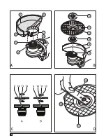
Fitting and removing the guard (fig. A)
K
G
912 Only
The tool is supplied with a guard intended for cutting off
purposes only. If the unit is intended to perform grinding
operations, a guard specific for this operation must be fitted. A
suitable guard for grinding operations part number
1004702-36
is available and can be obtained from BLACK & DECKER
service centres.
Fitting
u
Place the angle grinder on a table, spindle (5) up.
u
Align the lugs (8) with the notches (9).
u
Press the guard (4) down and rotate it to the required
position.
u
Securely tighten the screw (6).
u
To remove the guard, slacken the screw
Warning!
Never use the tool without the guard.
Fitting the side handle
u
Screw the side handle (2) into one of the mounting holes
in the tool.
Warning!
Always use the side handle.
Fitting and removing grinding or cutting discs
(fig. B - D)
Always use the correct type of disc for your application.
Always use discs with the correct diameter and bore size (see
technical data).
Fitting
u
Fit the guard as described above.
u
Place the inner flange (10) onto the spindle (5) as shown
(fig. B). Make sure that the flange is correctly located on
the flat sides of the spindle.
u
Place the disc (11) onto the spindle (5) as shown (fig. B).
If the disc has a raised centre (12), make sure that the
raised centre faces the inner flange.
u
Make sure that the disc locates correctly on the inner
flange.
u
Place the outer flange (13) onto the spindle. When fitting
a grinding disc, the raised centre on the outer flange must
face towards the disc (A in fig. C). When fitting a cutting
disc, the raised centre on the outer flange must face away
from the disc (B in fig. C).
u
Keep the spindle lock (3) depressed and tighten the outer
flange using the two-pin spanner (14) (fig. D).
Removing
u
Keep the spindle lock (3) depressed and loosen the outer
flange (13) using the two-pin spanner (14) (fig. D).
u
Remove the outer flange (13) and the disc (11).
Fitting and removing sanding discs (fig. D & E)
For sanding, a backing pad is required. The backing pad is
available from your BLACK+DECKER dealer as an accessory.
Fitting
u
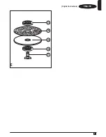
Place the inner flange (10) onto the spindle (5) as shown
(fig. E). Make sure that the flange is correctly located on
the flat sides of the spindle.
u
Place the backing pad (15) onto the spindle.
u
Place the sanding disc (16) onto the backing pad.
u
Place the outer flange (13) onto the spindle with the raised
centre facing away from the disc.
u
Keep the spindle lock (3) depressed and tighten the outer
flange using the two-pin spanner (14) (fig. D). Make sure
that the outer flange is fitted correctly and that the disc is
clamped tightly.
Removing
u
Keep the spindle lock (3) depressed and loosen the outer
flange (13) using the two-pin spanner (14) (fig. D).
u
Remove the outer flange (13), the sanding disc (16) and
the backing pad (15).
Use
Warning!
Let the tool work at its own pace. Do not overload.
u
Carefully guide the cable in order to avoid accidentally
cutting it.
u
Be prepared for a stream of sparks when the grinding or
cutting disc touches the workpiece.
u
Always position the tool in such a way that the guard
provides optimum protection from the grinding or cutting
disc.
Switching on and off
u
To switch on, slide the on/off switch (1) forward. Note that
the tool will continue running when you release the switch.
u
To switch off, press the rear part of the on/off switch.
Warning!
Do not switch the tool off while under load.
Soft Start Feature
The soft start feature allows a slow speed build-up to avoid
an initial jerk when starting. This feature is particularly useful
when working in confined spaces.
No-Volt
The No-volt function stops the grinder restarting without the
switch being cycled if there is a break in the power supply.

