background image

7

8

9

11

10

Go To Step 13

Go To Step 13

STOP

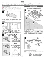
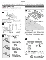
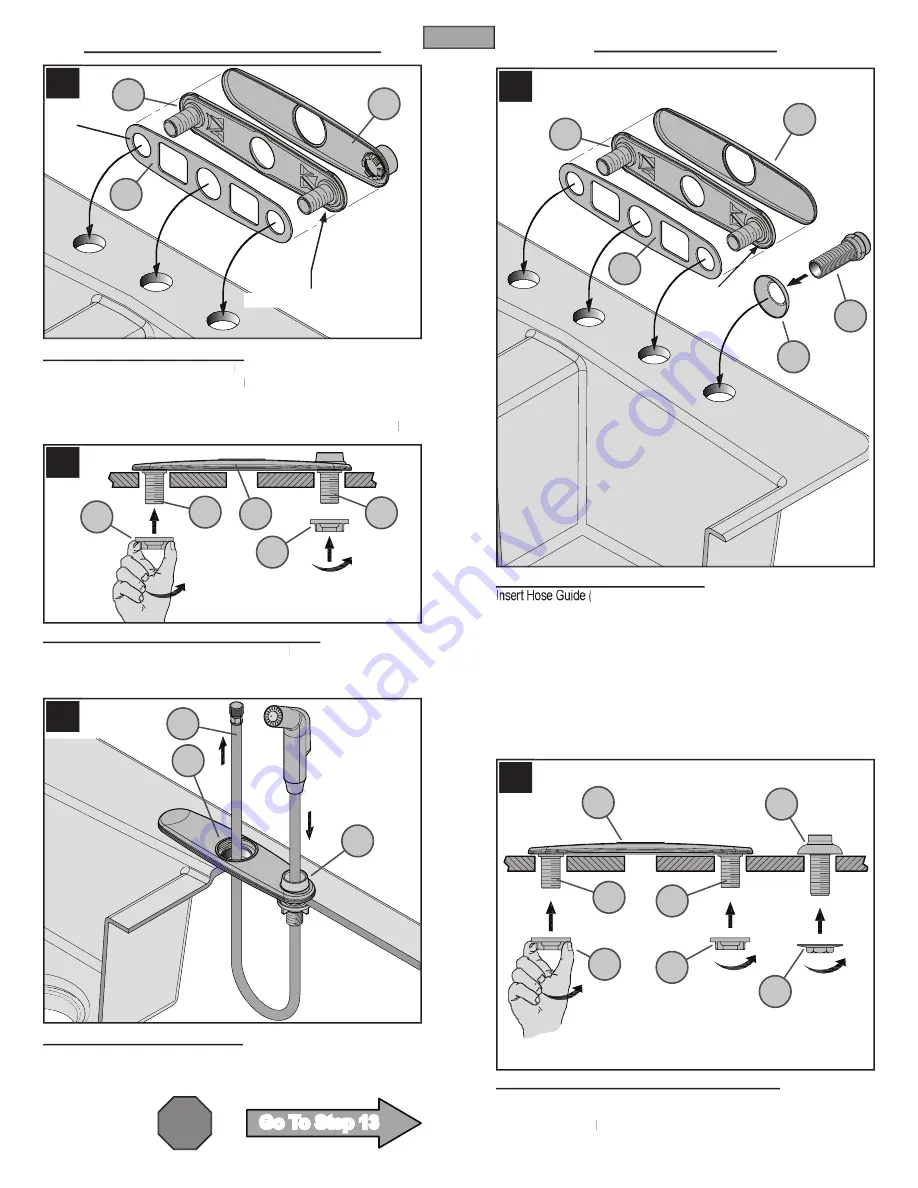
3 HOLE INSTALLATION WITH SIDE SPRAY

7   DECKPLATE INSTALLATION

Ensure that the Plastic Putty Plate (

7A

77

) is pressed on the Deckplate (

7B

).  

Place Gasket (

7C

) under Putty Plate (

7A

77

).  Install Deckplate (

7B

) over the 

three holes in your sink.

♦ Note:

 If you prefer to use Plumber’s Putty discard Gasket (

7C

) and apply a bead 

of plumber’s putty in the groove along the outer edge of the Putty Plate (

7A

77

).

8   SECURING DECKPLATE & HOSE GUIDE

From underneath sink, hand tighten Wing Nuts (

8A

88

) to Mounting Posts (

8C

).  

Caution: do not over-tighten wing nuts.

  Remove any excess putty from 

around the outside edge of Deck Plate (

8B

).

9   SIDE SPRAY INSTALLATION

Insert the Side Spray Hose (

9A

) through the Hose Guide (

9B

).  From underneath 

sink, feed the Side Spray Hose (

9A

) back up through the center hole of sink 

and through Deckplate (

9C

) so that it is above the sink.

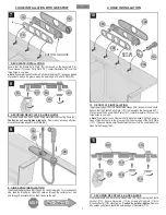
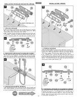
4 HOLE INSTALLATION

10   DECKPLATE INSTALLATION

10A

) into Hose Guide Flange (

10B

) and onto the sink hole.   

Ensure that the Plastic Putty Plate (

10C

) is pressed on the Deckplate (

10D

).  

Place Gasket (

10E

) under Putty Plate (

EE

10C

).  Install Deckplate (

10D

) over the 

three holes in your sink.  

♦ Note:

 If you prefer to use Plumber’s Putty discard Gasket (

10E

) and apply a 

EE

bead of plumber’s putty in the groove along the outer edge of the Putty Plate 

(

10C

).  If desired, place a small bead of plumber’s putty to the underside of the 

Hose Guide Flange (

10B

).

11   SECURING DECKPLATE & HOSE GUIDE

From underneath sink, secure the Hose Guide (

11A

) by screwing the Plastic 

Locknut (

11C

).  Secure Deckplate (

11D

) by screwing Wing Nuts (

11E

) to 

Mounting Posts (

11F

).  Hand tighten.

11F

11F


Caution: do not over-tighten.

  Remove 

any excess putty from around the outside edge of Deckplate (

11D

). 

3

ENGLISH

7A

7B

9A

9C

9B

7C

8B

8A

8A

8C

8C

BOTTOM GROOVE

10D

10C

10E

BOTTOM 

GROOVE

10B

10A

A

11C

11D

11F

11E

11F

11E

11A
Summary of Contents for Price Pfister Parisa 34-1N

Page 1: ...eur de Cuisine 03 02 05 EO6622W 27131 0200 A COMPANY A COMPANY A COMPANY A COMPANY A COMPANY A COMPANY A COMPANY A COMPANY A COMPANY A COMPANY A COMPANY A COMPANY A COMPANY A COMPANY A COMPANY A COMPANY A COMPANY A COMPANY A COMPANY Copyright 2005 Price Pfister Inc 2005 Price Pfister Inc ...

Page 2: ...MENDED Plumber s putty Slotted screwdriver Philips head screwdriver Pliers Adjustable wrench Flashlight Cloth Your installation may require new supply lines and or shut off valves or other additional tools These instructions cover three different installations INSTALLATION Go To Step 14 Go To Step 14 STOP 5 DECKPLATE INSTALLATION Ensure that the Plastic Putty Plate 5A is pressed on the Deckplate 5...

Page 3: ...ate 9C so that it is above the sink 4 HOLE INSTALLATION 10 DECKPLATE INSTALLATION 10A into Hose Guide Flange 10B and onto the sink hole Ensure that the Plastic Putty Plate 10C is pressed on the Deckplate 10D Place Gasket 10E under Putty Plate E under Putty Plate E 10C Install Deckplate 10D over the three holes in your sink Note If you prefer to use Plumber s Putty discard Gasket 10E and apply a E ...

Page 4: ...D on the Faucet Body 14E align with the Flats 14E align with the Flats 14E 14F on the 14F on the 14F Deckplate 14B 15 MOUNTING HARDWARE INSTALLATION From underneath sink secure the faucet by placing the Metal Washer 15A and the Long Nut 7 From underneath sink secure the faucet by placing the Metal Washer 7 From underneath sink secure the faucet by placing the Metal Washer 16 Hex 15B onto the Mount...

Page 5: ...e will increased to fully hot 19 SPOUT FUNCTION The Spout 19A 19A 19 can be rotated around the Faucet Body in any direction 20 SIDE SPRAY OPERATION For products with side spray The Side Spray 20A can be pulled forward to spray water in any direction To activate the Side Spray press the Toggle Button 20B located on the back of the Side Spray 20A 21 FLUSHING AERATOR CLEANING After installation is co...

Page 6: ...ll Price Pfister Consumer Service 3 Always turn off water and relieve pressure before working on your faucet NOTE Trim Care Cleaning Instructions For all Handles and decorative finishes use only a soft damp cloth to clean and shine Use of polish detergents abrasive cleaners organic solvents or acid may cause damage Use of other than a soft damp cloth will nullify our warranty Special Trim Trim produ...

Page 7: ...OR LATERAL 1 ANTES DE PROCEDER ADVERTENCIA Antes de proceder lea completamente todas las instrucciones Price Pfister recomienda llamar a un profesional si no se está seguro acerca de cómo instalar este producto Este producto debe instalarse de acuerdo a los códigos de plomería y de construcción locales y estatales 2 CIERRE EL SUMINISTRO DE AGUA Ubique las entradas del suministro de agua y cierre la...

Page 8: ...a de la manguera 11A en la brida de la guía de la manguera y en el agujero del fregadero Verifique que la placa de plástico para la masilla 10C esté oprimida sobre la placa de cubierta 10D Coloque la junta 10E bajo la E bajo la E placa de plástico para la masilla 10C Instale la placa de cubierta 10D sobre los tres agujeros en el fregadero Nota Si prefiere usar masilla de plomero descarte la junta 10...

Page 9: ...de la placa de cubierta 14B o el anillo de montaje 14C Asegúrese de que las secciones planas 14D del cuerpo del grifo 14E se alineen con las secciones planas 14E se alineen con las secciones planas 14E 14F en la placa de cubierta 14F en la placa de cubierta 14F 14B o el anillo de montaje 14C 15 INSTALACIÓN DE LA CERRAJERÍA DE MONTAJE Desde abajo del fregadero sujete el grifo colocando la arandela ...

Page 10: ...etamente caliente 19 FUNCIÓN DEL SURTIDOR El surtidor 19A 19A 19 puede girarse alrededor del cuerpo del grifo en cualquier dirección 20 FUNCIONAMIENTO DEL ROCIADOR LATERAL Para los productos con el rociador lateral El rociador lateral 20A 20A 20 puede tirarse hacia adelante para rociar agua en cualquier dirección Para activar el rociador lateral oprima el botón basculante 20B situado en la parte p...

Page 11: ...nija 3 Palanquee cuidadosamente y retire el botón de la manija 32 pulg quite el tornillo de fijación 22C y retire la manija 22B 23 REEMPLAZO DEL CARTUCHO Cierre los suministros de agua y alivie la presión antes de trabajar en el grifo consulte el paso 2 Retire la manija consulte el paso de arriba Quite la tapa en forma de cúpula 23A 23A 23 destornillándola en sentido contrahorario Destornille el an...

Page 12: ...mbier Tournevis plat Tournevis cruciforme Pince Clé à molette Lampe de poche Chiffon L installation peut exiger des tuyaux d arrivée et ou des vannes d arrêt neufs ou d autres outils INSTALLATION 5 POSE DE L APPLIQUE 5 POSE DE L APPLIQUE S assurerquelaplaquedemasticageenplastique 5A estappuyéesurl applique 5B Placez la garniture de joint 5C sous la plaque comptoir 5B Mettre l applique 5B en place ...

Page 13: ...ide de flexible 10A dans sa bride 10B et dans le trou de l évier S assurer que la plaque de masticage en plastique 10C est appuyée sur l applique 10D Placezlagarnituredejoint 10E sousla E sousla E masticageenplastique 10C Mettre l applique 10D en place par dessus les 3 trous de l évier Avis Si préfé fé f rez utiliser le mastic de plomberie abandonnez la garniture de joint 10E etappliquezunepetitego...

Page 14: ...n dans le trou central de l applique 14B ou dans l anneau de montage 14C S assurer que les pans 14D du corps de mitigeur 14E et ceux 14E et ceux 14E 14F de l applique 14F de l applique 14F 14B ou de l anneau de montage 14C sont alignés 15 POSE DU PETIT MATÉRIEL DE MONTAGE Depuis le dessous de l évier fixer le mitigeur en plaçant la rondelle métallique 15A et l écrou long 6 pans 7 16 po 15B sur la t...

Page 15: ... ce que celle ci soit très chaude 19 FONCTIONNEMENT DU BEC Le bec 19A 19A 19 peut pivoter dans n importe quel sens autour du corps du mitigeur 20 FONCTIONNEMENT DE LA DOUCHETTE LATÉRALE Pour des produits avec le douchette latérale La douchette latérale 20A peut être tirée vers l avant pour pulvériser de l eau dans toute direction Pour l activer appuyer sur la bascule 20B qui se trouve au dos de la...

Page 16: ...couper l arrivée d eau et dépressuriser avant de travailler sur le mitigeur voir l étape 2 Retirer la manette voir l étape 22 et le capuchon bombé 24B puis soulever le bec 24C avec précaution Le mécanisme de dérivation 24A se trouve à l arrière du corps intérieur de mitigeur 24D Retirer le mécanisme de dérivation 24A avec précaution pour voir s il est encrassé Nettoyer ou remplacer le mécanisme de...

Page 17: ...s Finish Letter Designates Finish La Letra Indica el Terminado La Letra Indica el Terminado La Lettre Designe La Fini La Lettre Designe La Fini A Polished Chrome Cromo Pulido Chrome Poli S Stainless Steel Acero Inoxidable Acier Inoxydable W White Blanco Blanc For products with side spray 951 050 Para los produc tos que contienen rociador lateral Pour les produits qui contiennent douchette latéral ...

Reviews: