background image

Chapter 2: Overview 

877-877-2269   |   blackbox.com 

Page 7

2. Welcome

Thank you for choosing the Black Box Central Power Hub. 
In tune with your network, as KVM systems expand so 
too do their requirements for the reliable supply of 
power. While individual Black Box power adaptors per-
form well, as devices proliferate they can become 
unwieldy and difficult to manage. Central Power Hub 
provides the next step in terms of efficiency, reliability 
and power management. 

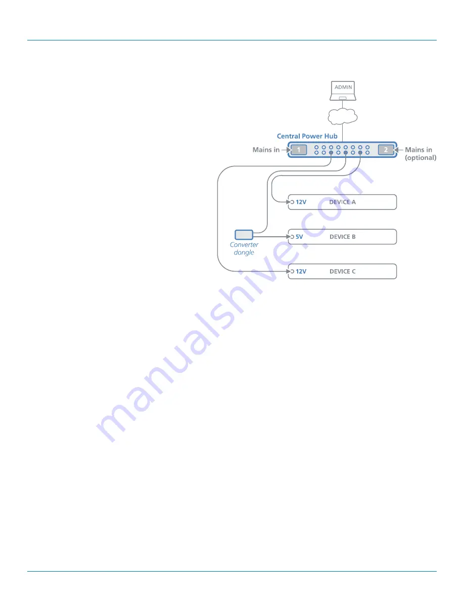
The heart of the Central Power Hub system is a modular 
chassis which occupies a 1U 19” rack slot. Arranged 
along its rear panel are eight or sixteen low voltage out-
put ports. These ports are then linked via cables and/or 

Converter dongles 

to the devices that require power. Each 

output has a nominal power rating of 20W. 

The overall power is generated within the main chassis by 
either one or two plug-in 460W power modules. Adding 
the optional second power module provides redundancy 
for mission critical installations. During normal operation, 
the overall load is shared between the twin power mod-
ules, with the full load transferring instantly to one if the 
mains supply to the other should fail.  

2.1 Protection and control

Power integrity, safety and management are core elements of the Central Power Hub system. The main chassis features a central 
microprocessor which manages all aspects of Central Power Hub operation. At start up it checks the validity of the single (or dual) 
power module(s) and then enables them. It then energizes each of the power ports in a carefully coordinated sequence to reduce 
the instantaneous load on the power module(s). After start up, each power port is carefully monitored to ensure safety protection 
while also maintaining power consistency to the multiple devices:

• 

Electronic short protection

 - If an overload or short circuit occurs on any output, the power is limited to a safe value (by cur-

rent pulsing) until the microprocessor recognizes the overload condition and trips the output – this happens approximately one 
second after the fault happens. Once this occurs, you will need to correct the source of the short circuit and then reinstate the 
output either via the front panel CLEAR button or the management application. The other power output ports will remain 
unaffected during this period.

• 

5V overload protection

 - Where an optional converter dongle is used to supply a 5V device, an extra layer of vigilance is 

brought into play. If the load on a dongle exceeds approximately 5.5A, then an internal circuit will trip to protect the power 
modules and the cabling. Once the cause is dealt with, a simple toggling of the power port will restore output.   

• 

Limited power source (LPS)

 - Further automated protection circuits within the Central Power Hub unit ensure that it fully 

complies with the IEC60950-1 regulation to operate as a Limited Power Source. 

The modular 460W power modules are unique; the central microprocessor circuit reads the unique code from a register in each 
power module and will only enable them once the correct code is received.

Available anywhere, via the in-built Ethernet port, a browser-based management application allows authorized admin users to 
monitor and control the power module(s) and all of the individual power output ports. 

2.2 5VDC converter dongles

Each power output port operates at 12VDC. For devices that use 12VDC, a simple connection cable (ACR1000-3PL-CBL2M) is all 
that’s required to link them to each power port. However, numerous Black Box devices operate at a lower voltage of 5VDC and 
these each require the use of a converter dongle (ACR1000-12V5-CBL2M) to take the place of the simple connection cable. 

Summary of Contents for ACR1000-12V5-CBL2M

Page 1: ...dant operation Central Power Hub ACR1000 CPH8R ACR1000 CPH16R ACR1000 12V5 CBL2M ACR1000 3PL CBL2M ACR1000 CPH PS Order toll free in the U S or for FREE technical support 24 7 Call 877 877 BBOX outsid...

Page 2: ...nc Any other trademarks mentioned in this manual are acknowledged to be the property of the trademark owners We re here to help If you have any questions about your application or our products contact...

Page 3: ...en the equipment is operated in a commercial environment Operation of this equipment in a residential area is likely to cause interference in which case the user at his own expense will be required to...

Page 4: ...dan el flujo de aire por los orificios de ventilaci n 10 El equipo el ctrico deber ser situado fuera del alcance de fuentes de calor como radiadores registros de calor estufas u otros aparatos incluye...

Page 5: ...3 3 Fitting removing a power module 11 3 4 Network connection 12 4 Configuration 13 4 1 Accessing the management application 13 4 2 The Status Control page 14 4 3 The General Configuration page 16 4...

Page 6: ...following options are available Central power hub unit with 8 output ports Part number ACR1000 CPH8R Central power hub unit with 16 output ports Part number ACR1000 CPH16R 5VDC converter dongle with 6...

Page 7: ...ower consistency to the multiple devices Electronic short protection If an overload or short circuit occurs on any output the power is limited to a safe value by cur rent pulsing until the microproces...

Page 8: ...tails Consult the precautions listed within the Safety information section 3 1 Mounting converter dongles For each device that requires a 5VDC supply 12VDC devices require only a sim ple cable a Conve...

Page 9: ...000 3PL CBL2M cable to the power input socket of the device the lead is 2m 6 5 feet in length 2 Connect the locking 3 pin plug at the other end of the cable to one of the power output sockets on the r...

Page 10: ...will be pow ered An optional elongated rack bracket is available to allow the dongle to be mounted immediately behind the device 2 Connect the 2 5mm power jack of the dongle to the power input socket...

Page 11: ...tatic precautions remove the new power module from its packing 3 Carefully slide the power module into the vacant bay until the locking clip clicks to hold the module in place 3 3 2 To remove a power...

Page 12: ...ote The patch cable used to link with the Central Power Hub must be screened to the S FTP level 3 4 1 To connect to a network 1 Use a screened patch cable cross over or straight connections are both s...

Page 13: ...r computer and enter the IP address of the Central Power Hub The default IP address setting is 192 168 1 22 3 If requested enter your username and password to log on Note The default username and pass...

Page 14: ...rol each output port individually Key metrics for the single or dual power module s including the temperatures cooling fan speeds mains input and low voltage output currents Click the required menu it...

Page 15: ...s appropriate click either the ALL ON or ALL OFF button 2 Click OK to confirm your choice in the subsequent popup Note When the ALL ON button is pressed the individual ports will be energized in a sta...

Page 16: ...ower modules apply their full supply to the Central Power Hub chassis This feature is useful when multiple Central Power Hub units are fed from the same mains power feed By staggering the switch on po...

Page 17: ...DHCP Dynamic Host Configuration Protocol to automatically determine all network settings and all other options in this page will be grayed out When unticked use the other options to configure the netw...

Page 18: ...ration page is ticked 4 5 1 To add a new user 1 Enter a User Name and Password and then Confirm password in the labeled fields Note The User Name and Password fields accept ASCII characters only UTF 8...

Page 19: ...ntral Power Hub unit equivalent to a cold reboot as if power to it had been removed and restored All power outputs will be removed and then restored in a staggered manner defined by the start up delay...

Page 20: ...ory Reset button 2 Click OK to confirm your choice in the subsequent popup 4 6 3 Firmware update This option will perform an update to the firmware contained within the logic circuitry of the Central...

Page 21: ...th of the power modules is an invalid type OVLD On An overload condition has been detected on one or more of the 12V output ports The port will have powered down After rectifying the cause press the r...

Page 22: ...l Power Hub 2 Depending on where the trip was made you will see different results If the Central Power Hub electronic short protection circuit responded the front panel OVLD indicator will be lit and...

Page 23: ...wer Hub unit equivalent to a cold reboot All power outputs will be removed and then restored in a staggered manner as defined within the management application No configuration details will be changed...

Page 24: ...powering Replace the power adapter with a manufacturer approved type only Do not use the power adapter if the power adapter case becomes damaged cracked or broken or if you suspect that it is not ope...

Page 25: ...Appendices 877 877 2269 blackbox com Page 25...

Page 26: ...ve 24 7 Tech support available in 60 seconds or less Copyright 2020 Black Box Corporation All rights reserved Black Box and the Double Diamond logo are registered trademarks of BB Technologies Inc Any...

Reviews: