background image

11

1.877.877.2269

BLACKBOX.COM

NEED HELP?

LEAVE THE TECH TO US

LIVE 24/7

TECHNICAL

SUPPORT

1.877.877.2269

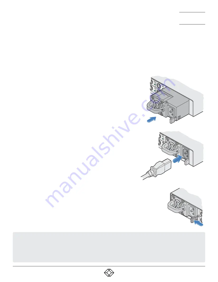
3.4 FITTING/REMOVING A POWER MODULE

The Central Power Hub main chassis can accommodate two power modules, although operation is perfectly possible with just one 
module fitted. The addition of a second module provides redundancy for critical installations. 

IMPORTANT: To ensure correct and reliable operation, only approved power modules may be used with the Central Power Hub.

Note: Module bay 1 is on the left as you view the rear of the Central Power Hub chassis, module bay 2 is on the right.

3.4.1 TO FIT A POWER MODULE

Note: Power modules are hot-pluggable (i.e. while power is applied to the other module), be 
sure to observe safe working practices and anti-static precautions when fitting a module to 
a working Central Power Hub chassis. 

1  If a blanking plate is fitted, remove it to reveal the power module bay. 

2  Observing suitable anti-static precautions, remove the new power module from its 

packing.

3  Carefully slide the power module into the vacant bay until the locking clip ‘clicks’ to hold 

the module in place.

3.4.2 TO REMOVE A POWER MODULE

Note: Power modules are hot-pluggable (i.e. while power is applied to the other module), be sure to 
observe safe working practices and anti-static precautions when removing a module from a working 
Central Power Hub chassis.

1  Isolate power from the module to be removed and disconnect the IEC power cord.

2  Push the locking lever to the left so that the module un-clips and use the handle to carefully pull the 

module out of the bay.

3  If no replacement module is to be used, fit a blanking plate to cover the vacant bay. 

4  Insert an IEC power cord into the socket on the module and apply power to the 

module.

IMPORTANT: Please read and adhere to the electrical safety information given within the Safety information section of this guide. In 
particular, do not use an unearthed power socket or extension cable.

Note: Various items within the Central Power Hub casing generate heat when in operation and will become warm to the touch. 
Ensure that air can circulate freely at the rear of the enclose, particularly by the power module cooling fans. Do not operate the 
equipment in ambient temperatures exceeding 50 degrees Centigrade. Do not place the products in contact with equipment whose 
surface temperature exceeds 50 degrees Centigrade. 

Summary of Contents for ACR1000-CPH-PS-R2

Page 1: ...USER GUIDE ACR1000 CPH8R R2 ACR1000 CPH16R R2 ACR1000 CPH PS R2 CENTRAL POWER HUB 24 7 TECHNICAL SUPPORT AT 1 877 877 2269 OR VISIT BLACKBOX COM...

Page 2: ...emarks of BB Technologies Inc Any other trademarks mentioned in this manual are acknowledged to be the property of the trademark owners We re here to help If you have any questions about your applicat...

Page 3: ...case the user at his own expense will be required to take whatever measures may be necessary to correct the interference Changes or modifications not expressly approved by the party responsible for co...

Page 4: ...reros o gabinetes que impidan el flujo de aire por los orificios de ventilaci n 10 El equipo el ctrico deber ser situado fuera del alcance de fuentes de calor como radiadores registros de calor estufa...

Page 5: ...erter dongles 8 3 3 Connections 9 3 4 Fitting removing a power module 11 3 5 Network connection 12 CHAPTER 4 CONFIGURATION 13 4 1 Accessing the management application 13 4 2 The Status Control page 14...

Page 6: ...or the reliable supply of power While individual Black Box power adaptors perform well as devices proliferate they can become unwieldy and diffi cult to manage Central Power Hub provides the next step...

Page 7: ...t either via the front panel CLEAR button or the management application The other power output ports will remain unaffected dur ing this period 5V overload protection Where an optional converter dongl...

Page 8: ...See below for details Consult the precautions listed within the Safety information section 3 2 MOUNTING CONVERTER DONGLES For each device that requires a 5VDC supply 12VDC devices require only a sim p...

Page 9: ...g at one end of the ACR1000 3PL CBL2M cable to the power input socket of the device the lead is 2m 6 5 feet in length 2 Connect the locking 3 pin plug at the other end of the cable to one of the power...

Page 10: ...e close to the device that will be pow ered An optional elongated rack bracket is available to allow the dongle to be mounted immediately behind the device 2 Connect the 2 5mm power jack of the dongle...

Page 11: ...s to hold the module in place 3 4 2 TO REMOVE A POWER MODULE Note Power modules are hot pluggable i e while power is applied to the other module be sure to observe safe working practices and anti stat...

Page 12: ...Power Hub allows remote monitoring and control via a standard network connection 3 5 1 TO CONNECT TO A NETWORK 1 Use a screened patch cable cross over or straight connections are both sup ported to l...

Page 13: ...a temporary connection see below 2 Run a web browser on your computer and enter the IP address of the Central Power Hub The default IP address setting is 192 168 1 22 3 If requested enter your usernam...

Page 14: ...u can monitor name and control each output port individually Key metrics for the single or dual power module s including the temperatures cooling fan speeds mains input and low voltage output currents...

Page 15: ...Power Output section As appropriate click either the ALL ON or ALL OFF but ton 2 Click OK to confirm your choice in the subsequent popup Note When the ALL ON button is pressed the individual ports wi...

Page 16: ...ed to the unit before the power modules apply their full supply to the Central Power Hub chassis This feature is useful when multiple Central Power Hub units are fed from the same mains power feed By...

Page 17: ...tral Power Hub will use DHCP Dynamic Host Configuration Protocol to automatically determine all network settings and all other options in this page will be grayed out When unticked use the other optio...

Page 18: ...within the General configuration page is ticked 4 5 1 TO ADD A NEW USER 1 Enter a User Name and Password and then Confirm password in the labeled fields Note The User Name and Password fields accept...

Page 19: ...the operation of the Central Power Hub unit equivalent to a cold reboot as if power to it had been removed and restored All power outputs will be removed and then restored in a staggered manner define...

Page 20: ...ORY RESET 1 Click the Factory Reset button 2 Click OK to confirm your choice in the subsequent popup 4 6 3 FIRMWARE UPDATE This option will perform an update to the firmware contained within the logic...

Page 21: ...ashing One or both of the power modules is an invalid type OVLD On An overload condition has been detected on one or more of the 12V output ports The port will have powered down After recti fying the...

Page 22: ...between it and the Central Power Hub 2 Depending on where the trip was made you will see different results If the Central Power Hub electronic short protection circuit responded the front panel OVLD...

Page 23: ...peration of the Central Power Hub unit equivalent to a cold reboot All power outputs will be removed and then restored in a staggered manner as defined within the management application No configurati...

Page 24: ...ering Replace the power adapter with a manufacturer approved type only Do not use the power adapter if the power adapter case becomes damaged cracked or broken or if you suspect that it is not oper at...

Page 25: ...COPYRIGHT 2021 BLACK BOX CORPORATION ALL RIGHTS RESERVED NEED HELP LEAVE THE TECH TO US LIVE 24 7 TECHNICAL SUPPORT 1 877 877 2269 877 877 2269 blackbox com ACR1000 rev 1 0...

Reviews: