DSL LAN Extender 200 User’s Guide
© 2002 Black Box Corporation
Page 4
INSTALLATION
To install your DSL LAN Extender 200 devices, you need to use the following cable connection for each
device:
•
Supplied power supply
•
10Base-T cable
•
DSL telephone cable
•
Serial cable – you only need to connect a serial cable if you want to configure the DSL LAN Extender
device via a serial port connection. Most of the configuration can be set through the 10BaseT
connection, except for changing the Device Main IP address.
•
Please see the section below for Port Pin Layout of Console (RS-232), 10Base-T, and DSL LINE
ports.
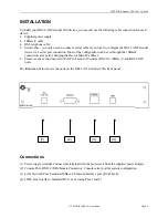
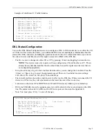
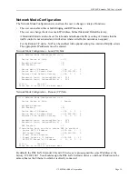
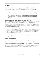
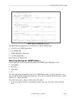
The illustration below shows the ports on the DSL LAN Extender 200’s back panel.
Connections
(1) Power supply terminal. Connect this terminal with the power jack from the supplied power adapter.
(2) Console Port, RS-232 (DB9 Female Connector): Console seria l port for system configuration.
(3) LAN Network Port: Standard 10Base-T Ethernet interface port (RJ-45 Jack).
(4) xDSL Line Interface: Standard RJ-11 Jack (using Pins 3 and 4).
(1)
(2)
(3)
(4)

