


Omnitron Systems Technology, Inc.3
FlexPoint
TM
Powered Chassis
User’s Manual
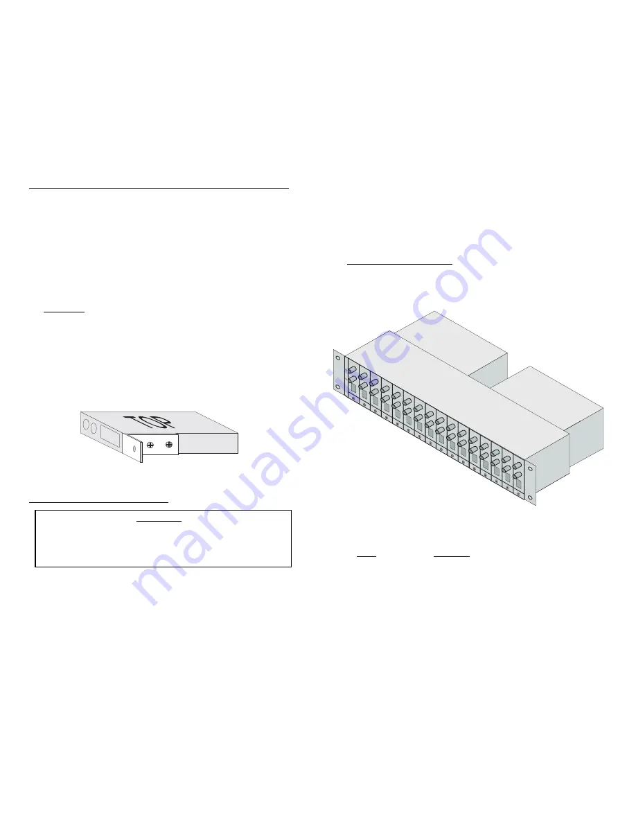
GENERAL DESCRIPTION
The FlexPoint
TM
Powered Chassis is a chassis capable of holding up to 14
FlexPoint
TM
media converter modules. It is equipped with two power supplies in a
power-redundant configuration.
This User’s Manual describes the following models:
Model
Description
LMC200A-2PS-DC
Powered Chassis, rack-mountable chassis, 2 power
supplies
LMC200A-DC
Powered Chassis, rack-mountable chassis, 1 power
supply
PSFP20-DC
Power supply unit for models LMC200A-2PS-DC and
LMC200A-DC
6
Cabling and Power-Up:
1. Insure that both FlexPoint Chassis power supply switches are in the OFF position.
2. Assure that the 48VDC circuit breaker can supply 3A of current per power supply.
3. Locate the 48VDC circuit breaker, and switch the 48VDC circuit breaker to the
OFF position.
4. Cut the power cable to the length required.
5. Strip approximately 3/8 of an inch of insulation from the power cable wires.
6. Connect the power cables to the FlexPoint Chassis by fastening the stripped
ends to the 48VDC connector.
WARNING:
Note the wire colors used for making the positive, negative and
ground connections. Use the same color assignment for the connection at the
circuit breaker.
7. Connect the power cable to the circuit breaker and switch the circuit breaker
ON.
8. Turn both FlexPoint Chassis power supply switches on and check the power
LED’s on the front panel of the powered chassis. The two LED’s should be ON.
9. Attach the L shaped tabs to the FlexPoint media converter units to be inserted
into the chassis, Secure the FlexPoint module using the enclosed screws.
10. Save the unused tabs in a safe place or secure them to the chassis’ unused
Slots.
POWER SUPPLY REPLACEMENT
WARNING!
NEVER ATTEMPT TO OPEN OR SERVICE THE POWER
SUPPLY UNIT. OPENING THE POWER SUPPLY UNIT
MAY CAUSE SERIOUS INJURY OR DEATH.
The Powered Chassis is intended to be used with two power supplies in a power-
redundant operation. A failure of a single supply should not disturb the operation
of the chassis unit. However, certain power supply failures may cause a
secondary failure to the associated fan and cause undesired overheating of
the chassis unit.


