35
CHAPTER 4: Operation and Troubleshooting
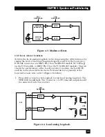
Figure 4-3. Modem self-test.
4.3.2 L
OCAL
A
NALOG
L
OOPBACK
Activate the local analog loopback test by depressing the ANA button or by
raising the level of the Local Loopback signal received by the Converter’s
DTE-side connector (on DB25 Pin 18 on the RS-530 models, M/34 Pin JJ
on the V.35 models, or DB37 Pin 10 on the V.36/RS-449 models). This test
checks the performance of the local Converter’s modem, the local DTE,
and the connections between them. Perform this test separately at the
local and remote sites (refer to Figure 4-4 below):
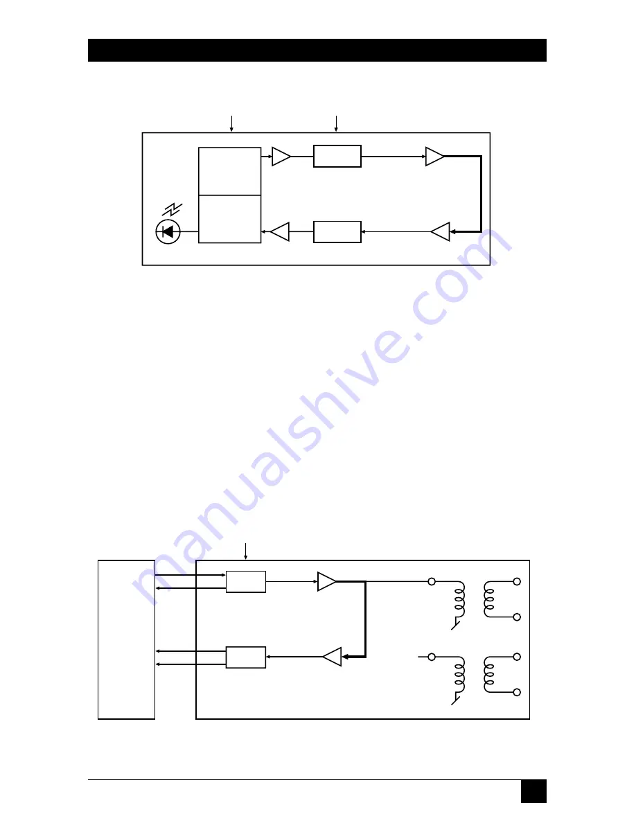
1. Press ANA or raise Local Loopback to start local analog loopback. The
TEST LED should light. The Converter’s G.703 transmit output should
be connected to its own receiver.
Figure 4-4. Local analog loopback.
ANA
DEPRESSED
DTE
XMTR
RCVR
LINE
DATA
CLK
CLK
DATA
PATTERN
GENERATOR
PATTERN
TESTER
ERROR
PATT
DEPRESSED
ANA
DEPRESSED
XMTR
RCVR


