40
G.703 CODIRECTIONAL CONVERTER
Appendix: Pinouts
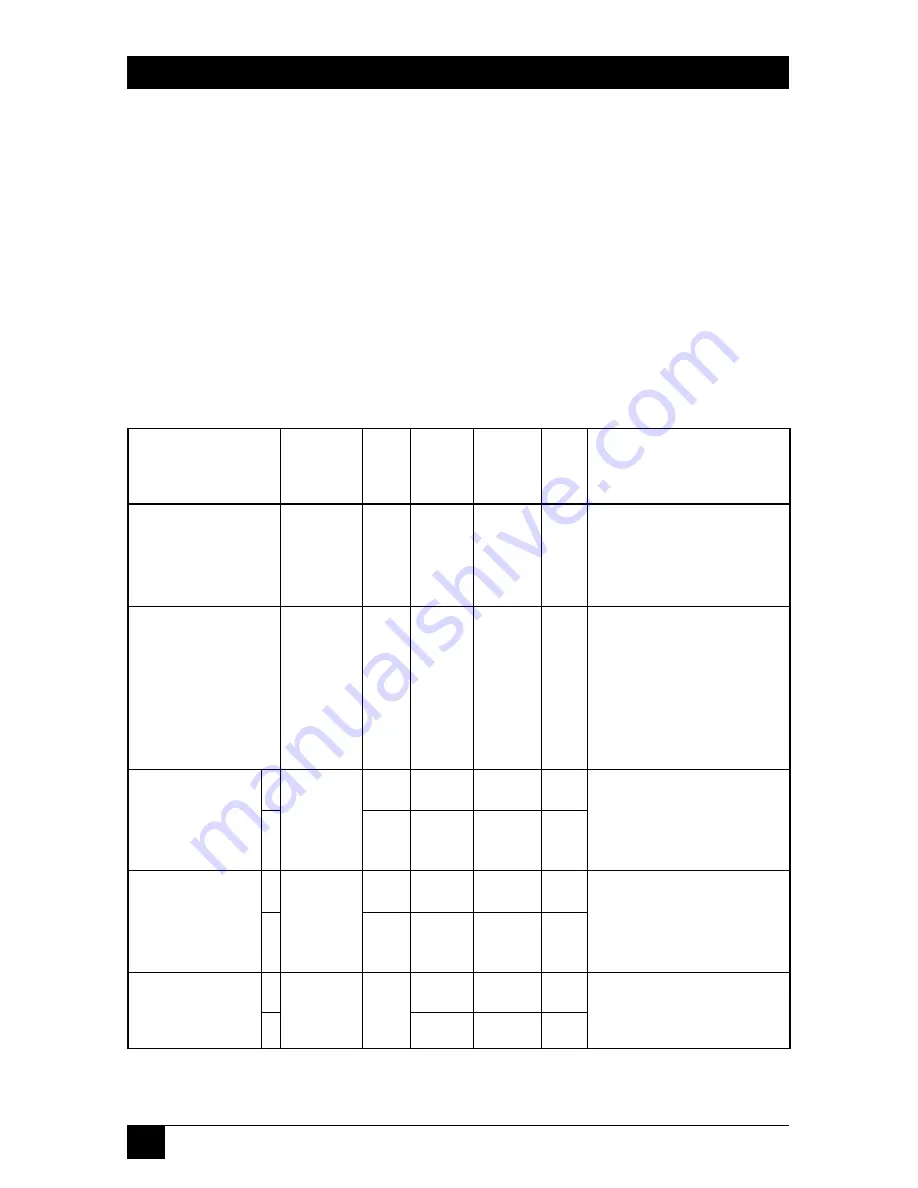
Table A-1 lists the signals and leads supported by the four Converter DTE
interfaces. Signals in different interfaces that are next to each other in this
table are analogous (that is, they perform roughly the same functions). This
means that the pinout of the RS-530-to-RS-449 adapter included with the RS-
449 models is also shown in this table; the adapter cable connects the RS-530
leads/signals to the V.36/RS-449 leads/signals listed beside them.
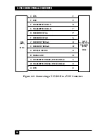
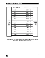
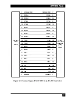
Figures A-1 through A-8 show how cables connecting different equipment
to the Converter’s interface connector should be pinned.
ITU-TSS
V.35 RS-530
V.36/
X.21
Circuit
Pin
Pin
RS-449
Pin
Pin(s)
101
A
1
1
1
102
B
7
19, 20,
8
37
103
P
2
4
2
S
14
22
9
104
R
3
6
4
T
16
24
11
105
C
4
7
3
19
25
10
Table A-1. Interface-Connector Pinouts
Description
Chassis ground. Can be
isolated from Signal Ground
or tied to it.
Common ground for
signaling and for the DC
power supply. Can be
isolated from Shield or tied
to it.
Serial digital data from the
DTE. The data transitions
must occur on the rising
edge of the transmit clock.
Serial digital data sent to the
DTE. The data transitions
occur on the rising edge of
the clock.
The DTE raises this signal
when it wants to send data
through the Converter.
Signal
Names
Shield, Frame
Ground (FGND),
Protective
Ground (PGND)
Signal Ground
(SGND, SG);
V.36/RS-449
only: also Send
Common (SC)
and Receive
Common (RC)
Send Data (SD),
Transmitted Data
(TD), Transmit (T)
Receive(d) Data
(RD), Receive (R)
Request to Send
(RTS, RS),
Control (C)
A
B
A
B
A
B


