Page 14
724-746-5500 | blackbox.com
Black Box LB200A-R4 User Manual
3.1
PLANNING THE INSTALLATION
To install the LB200A-R4 Ethernet Extender, do the following:
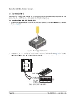
1. Connect the line interface between the units (refer to
“Connecting the Line Interface”
on page 14)
Note
See
Figure 2
for the LB200A-R4’s rear panel.
2. Connect the Ethernet interface (refer to
“Connecting the 10/100Base-T Ethernet Interface”
on
page 15).
3. Connect the power plug (refer to
“Connecting Power”
on page 16).
S
Figure 2 LB200A-R4 rear panel
3.2
CONNECTING THE LINE INTERFACE
CAUTION
The interconnecting cables shall be acceptable for external use
and shall be rated for the proper application with respect to volt-
age, current, anticipated temperature, flammability, and
mechanical serviceability.
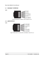
The LB200A-R4 supports communication between two peer Ethernet LAN sites over a distance of up to
10,000 ft (3 km) over 24 AWG (0.5 mm) twisted-pair wire, Cat5+, or 75-ohm BNC.
Note
Actual distance and link performance may vary depending on the environment and type/
gauge of wire used.
Follow the steps below to connect the LB200A-R4 interfaces.
Note
The LB200A-R4 units work in pairs. One of the units must be configured as a (L) Local unit,
and the other unit must be configured as a (R) Remote unit.
The Interconnecting cables shall be acceptable for external use
and shall be rated for the proper application with respect to volt-
age, current, anticipated temperature, flammability, and
mechanical serviceability.
CAUTION
Line
Ma
de
in
th
e U
SA
Eth
ern
et 1
Et
he
rn
et
0
Po
w
er
LB200A-R4
(Line: RJ-45)
Summary of Contents for LB200A-R4
Page 31: ......


