724-746-5500 | blackbox.com
Page 19
Configuration
4.3
CONFIGURING DIP SWITCH S1
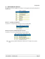
DIP switch S1 is where you configure the Line interface. The following tables describe the configuration for
the LB200A-R4.
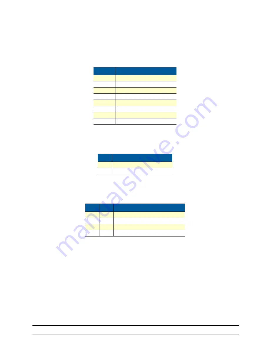
Table 1. S1 Summary
Position
Description
S1-1
Local/Remote Configuration
S1-2
Line Rate/Symmetry
S1-3
Line Rate/Symmetry
S1-4
Reserved
S1-5
SNR Margin
S1-6
Reserved
S1-7
Reserved
S1-8
Reserved
Switch S1-1: Local/Remote Configuration
Use switch S1-1 to configure the unit as Remote or Local in the LB200A-R4pair.
Table 2. Local/Remote Unit Configuration
S1-1
Setting
ON
CPE/Remote
OFF
CO/Local
Switches S1-2 and S1-3: Symmetric/Asymmetric Operation
Use switches S1-2 and S1-3 to configure the line rate type and operation.
Table 3. Symmetric/Asymmetric Selection Chart
S1-2
S1-3
Setting
OFF
OFF
High-Speed “Symmetric”
OFF
ON
High-Speed “Asymmetric”
ON
OFF
FastPath High-Speed “Asymmetric”
ON
ON
Long-Range “Asymmetric”
Note
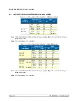
See “Line Rate & Reach Chart Based on 24 AWG (0.5 mm)” on page 30 for line rate dis-
tances.
Summary of Contents for LB200A-R4
Page 31: ......


