background image

14

3

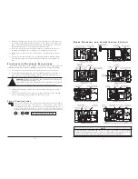
2) Black Box installs dust caps to ensure factory-clean optical devices.  These protective

caps should not be removed until the moment of connecting the fiber cable to the
device.  Assure that the fiber is properly terminated, polished and free of any dust or
dirt and that the location is as free from dust and dirt as possible.

3) Store spare caps in a dust free environment such as a sealed plastic bag or box so

that when reinstalled they do not introduce any contamination to the optics.

4) Should it be necessary to disconnect the fiber device, reinstall the protective dust

caps.

5) If you suspect that the optics have been contaminated, alternate between blasting

with clean dry compressed air and flushing with methanol to remove particles of
dirt.

E

L E C T R O S T A T I C

D

I S C H A R G E

P

R E C A U T I O N S

Electrostatic discharge (ESD) can cause damage to your add-in modules.  Always observe the

following precautions when installing or handling an add-in module or any board assembly

.

1) Do not remove unit from its protective packaging until you’re ready to install it.

2) Wear an ESD wrist grounding strap before handling any module or component.  If

you do not have a wrist strap, maintain grounded contact with the system unit
throughout any procedure requiring ESD protection.

WARNING!

Integrated circuits and fiber optic components are extremely suscepti-

ble to electrostatic discharge damage.  Do 
not handle these components directly unless you are a qualified service technician
and use tools and techniques that conform to accepted industry practices

.

3) Hold boards by the edges only; do not touch the electronic components or gold

connectors.

4) After removal, always place the boards on a grounded, static-free surface, ESD pad

or in a proper ESD bag.  Do not slide the board over any surface

.

S

A F E T Y

C

E R T I F I C A T I O N S

U

ULL//C

CU

ULL::

Listed to Safety of Information Technology Equipment, Including Electrical Business Equipment.

C

CEE::

The products described herein comply with the Council Directive on Electromagnetic
Compatibility (89/336/EEC) and the Council Directive on Electrical Equipment Designed for use
within Certain Voltage Limits (73/23/EEC).  Certified to Safety of Information Technology
Equipment, Including Electrical Business Equipment.  For further details, contact Black Box.

Class 1 Laser product,  Luokan 1 Laserlaite,  
Laser Klasse 1,  Appareil A’Laser de Classe 1

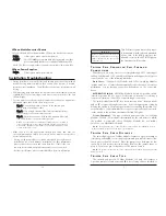
B

O A R D

D

I A G R A M S A N D

J

U M P E R

/ S

W I T C H

S

E T T I N G S

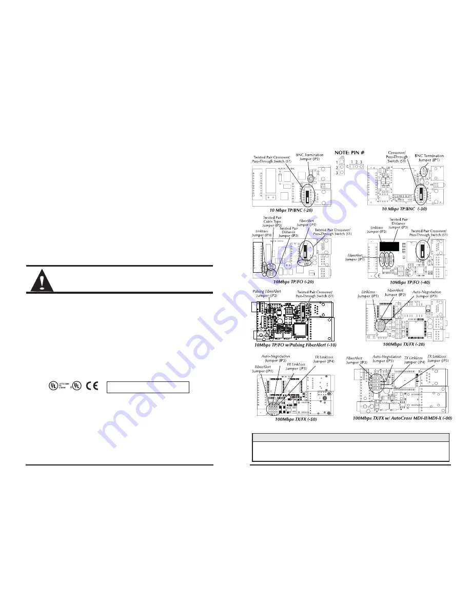
NOTE

To determine which board diagram (-20, -40, -50, etc.) matches your module, compare the jumper
locations with the diagrams found above.

10/100 Switching modules 

and 

Gigabit modules

do not

require any configuration, therefore the boards for those modules are not shown above.

Summary of Contents for LE740-TPSTM-R2

Page 1: ... LE740 TPBNC TP BNC NOTE All modules support half and full duplex except modules with BNC connectors are always HDX N O T E This manual will refer to all types of modules as Media Conversion Modules except where differences require indi catation Q U I C K S T A R T Introduction 1 Board Diagrams 3 Jumper Settings 4 Crossover Pass Through 5 LinkLoss FiberAlert 6 Auto Negotiation 8 Installation of Mo...

Page 2: ...G741 TXLXSC 13 TX SSLX SM1310 SC 10 Km LG741 TXLXSC 15 TX SSLX SM1550 SC 10 Km LG741 TXLXSC 1340 TX SSLX SM1310 PLUS SC 40 Km LG741 TXLXSC 1540 TX SSLX SM1550 PLUS SC 40 Km Configuring Media Conversion Modules Before installing you can configure 10Mbps and 100Mbps Modules for a variety of features see diagrams chart on page 3 4 for specific informa tion 10 100 Switching and Gigabit Modules have pl...

Page 3: ...iring ESD protection WARNING Integrated circuits and fiber optic components are extremely suscepti ble to electrostatic discharge damage Do not handle these components directly unless you are a qualified service technician and use tools and techniques that conform to accepted industry practices 3 Hold boards by the edges only do not touch the electronic components or gold connectors 4 After remova...

Page 4: ...N C P O R T T E R M I N A T I O N 10Mbps modules with BNC ports feature a 2 pin jumper block located at position JP1 or JP2 for terminating a thin coaxial segment at the media converter without an additional T con nector and terminator Jumper position is dependent on board revision see chart above To terminate a thin Ethernet segment at the media converter attach the cable directly to the BNC conn...

Page 5: ...d If the BNC port is not ter minated correctly the ACTIVITY light on the front panel will not glow T W I S T E D P A I R C R O S S O V E R P A S S T H R O U G H C O N N E C T I O N S Whether you are using crossover or straight through CAT5 twisted pair cabling 10Mbps and 10 100 Switching Modules will support both types of connections by one of the following methods AutoCross 100Mbps 00 Modules and...

Page 6: ... the cable to the other device is intact and the link pulses are reaching the other end The combination of FiberAlert and LinkLoss allows this information to be obtained even when physical access to a remote device and its link integrity LED is not available W H A T I S F O F X L I N K L O S S FO FX LinkLoss is a troubleshooting feature When a fault occurs on the fiber segment of a conversion FO F...

Page 7: ...ir link TP TX LinkLoss disables the transmitter on the media converter s fiber port This results in a loss of link on the device con nected to the fiber port W H A T I S F I B E R A L E R T FiberAlert minimizes the problems associated with the loss of one strand of fiber If a strand is unavailable the Black Box device at the receiver end notes the loss of link The device will then stop transmittin...

Page 8: ... I S O N T A B L E Feature Fault Location Disabled LEDs Enable At FX LinkLoss Fiber Twisted Pair Main Site Only TX LinkLoss Twisted Pair Fiber Remote Site Only FiberAlert Fiber Fiber Remote Site Only A U T O N E G O T I A T I O N O N 1 0 1 0 0 S W I T C H I N G M O D U L E S Auto Negotiation is a standard feature on 10 100 Switching Modules The fiber port always operates at 100 Mbps FDX the copper...

Reviews: