7
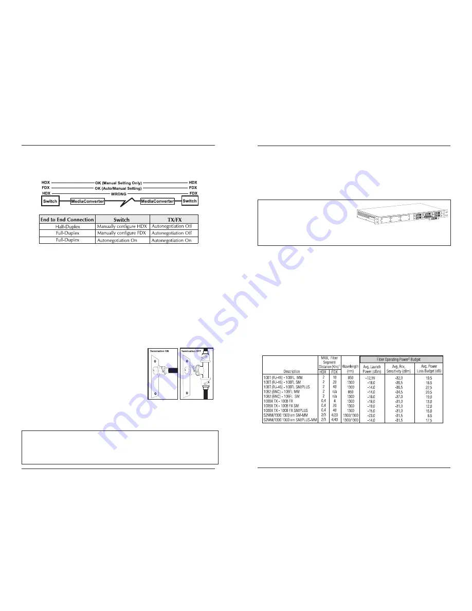
and Full-Duplex settings must be manually set and match on both devices
the media converters are connected to (see below). The diagram below
show a typical application, followed by a table with three possible
configurations.
Autonegotiation
is configured with a 3-pin jumper block located at
position JP3 on
100 Mbps Modules
. Enable
Autonegotiation
by placing the
shunt over pins 1-2. Disable
Autonegotiation
(factory default) by placing the
shunt over pins 2-3.
BNC Port Termination
10 Mbps Modules
with BNC ports feature a 2-pin jumper block located at
position JP1. This jumper block allows a thin coaxial segment to be termi-
nated at the
Media Converter
without an additional ‘T’ connector and
terminator. If a thin Ethernet segment is to be terminated at the BNC port
on the
Media Converter
, attach the cable directly to the BNC connector and
set the termination jumper to the ON (enabled, factory default) position by
placing the shunt over both pins.
If the BNC port on the
Media Converter
is attached to a midpoint of a
thin Ethernet segment, attach a ‘T’ connector to
the BNC port and set the termination jumper to
the OFF (disabled) position by placing the shunt
on only one pin or by removing the shunt.
Note: Thin Ethernet segments must be properly
terminated at both ends and grounded at one end.
If the BNC port is not terminated correctly, the
ACTIVITY light on the front panel will not glow.
Installing Media Conversion Modules
Media conversion modules can be installed in any available media
conversion module slot. Media conversion modules are hot-swappable.
Note: S2MM Module Sets can be installed in any two available slots, but still must
be used as a set to provide a complete conversion. We recommend that each
S2MM Module Set be installed side-by-side (left-to-right or top-to-bottom) to
prevent mismatching module sets. It is necessary to power the unit down before
configuration.
8
Media conversion modules are shipped with brackets for securing them
to the
Media Converter
chassis. Media conversion modules attach to a
connector inside the
Media Converter
chassis. To install a module, simply
unscrew the blank bracket covering the slot where the module is to be
installed, slide the module into the chassis, via the cardguides, until the
module is seated securely in the connector. Secure the module to the
chassis by tightening the screws. Then connect the cables.
NOTE: Media Converter chassis are
shipped from the factory with all but
one media conversion module slot
covered with “blank” brackets. Be sure
to keep unused slots covered for EMI
containment. It is a good idea to save any “blanks” removed during installation
for future use if configuration requirements change.
Measuring for Oversaturation
The high power fiber transmitters used on
SingleMode/PLUS
media
conversion modules can overdrive the receivers and cause data loss if used
in installations where cable power losses are low. To verify this, measure
the optical power at the receiver. The measured power should be no
greater than -14dBm and no less than the Average Receive Sensitivity (listed
in the chart above). If measured power is greater than -14dBm, install an
optical attenuator to bring power within specification. Ideally,
SingleMode/PLUS
should be used only where total attenuation of fiber,
connectors and patch cords is greater than 7dB.
Determining Your Power Budget
The maximum distance for a fiber link is determined by the module
installed. The following chart shows the specifications for each of the
available modules:
1 Distances listed are estimates and can vary with application. Distance limitations are determined
by a combination of power budget fiber characteristics, number of connections and other
physical parameters. Subtract 3 dB from Power Loss Budget for 50/125
µ
multi-mode fiber. Half-
Duplex (HDX) distance is limited by IEEE specifications.
2 Values are averages and have been determined under factory conditions. Actual field
application values may vary.
MediaConverter/12x, Front View


