background image

11

1.877.877.2269

BLACKBOX.COM

NEED HELP?

LEAVE THE TECH TO US

LIVE 24/7

TECHNICAL

SUPPORT

1.877.877.2269

CHAPTER 3: INSTALLATION

WARNING REGARDING EARTHING GROUND:

o

o

o

o

This equipment shall be connected to the DC supply

system earthing electrode conductor or to a bonding
jumper from an earthing terminal bar or bus to which the
DC supply system earthing electrode is connected.

This equipment shall be located in the same immediate

area (such as adjacent cabinets) as any other equipment
that has a connection between the earthed conductor of
the same DC supply circuit and the earthing conductor,
and also the point of earthing of the DC system. The DC
system shall not be earthed elsewhere.

The DC supply source is to be located within the same

premises as this equipment.

There shall be no switching or disconnecting devices in

the earthed circuit conductor between the DC source and
the earthing electrode conductor.

Locate the DC circuit breaker of the external power source, and switch the circuit breaker to the OFF position.
Prepare a power cable using a three conductor insulated wire (not supplied) with 12 AWG to 14 AWG thickness. Cut the power cable  
to the length required.
Strip approximately 3/8 of an inch of insulation from the power cable wires.
Connect the power cables to the terminal by fastening the stripped ends to the DC power connector.
WARNING: Note the wire colors used in making the positive, negative, and ground connections. Use the same color assignment  
for the connection at the circuit breaker.
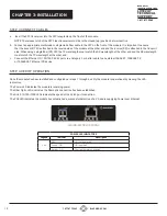
Secure the grounding wire to the ground screw.  See the figure below for the location of the grounding screw.

REAR VIEW OF THE LGC5700A WITH DC TERMINAL CONNECTOR

Connect the power wires to the circuit breaker and switch the circuit breaker ON. If any modules are installed, the Power LED should 
indicate the presence of power.
Installation of the equipment should be such that the air flow in the front, back, side, and top vents of the chassis are not compromised 
or restricted.

NEVER ATTEMPT TO OPEN THE CHASSIS OR

SERVICE THE POWER SUPPLY. OPENING THE

CHASSIS MAY CAUSE SERIOUS INJURY OR DEATH.

THERE ARE NO USER REPLACEABLE OR

SERVICEABLE PARTS IN THIS UNIT.

WARNING!!!

Summary of Contents for LGC5600A

Page 1: ...24 7 TECHNICAL SUPPORT AT 1 877 877 2269 OR VISIT BLACKBOX COM USER MANUAL LGC5600A LGC5700A GIGABIT ENET POE MEDIA CONVERTER ...

Page 2: ...1 2 LGC5600A MEDIA CONVERTER 3 1 3 LGC5700A INDUSTRIAL MEDIA CONVERTER 4 2 OVERVIEW 5 2 1 INTRODUCTION 5 2 2 INSTALLATION PROCEDURE OVERVIEW 6 3 INSTALLATION 7 Step 1 Configure DIP Switches 7 Step 2 Apply Power 10 Step 3 Connect Cables 12 Step 4 Verify Operation 12 A 1 FCC STATEMENT 14 A 2 NOM STATEMENT 15 B 1 DISCLAIMER 16 B 2 TRADEMARKS USED IN THIS MANUAL 16 ...

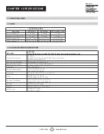
Page 3: ...62 A at 120 VAC typical Dimensions 1 0 H x 4 5 W x 6 0 D 2 5 x 11 4 x 15 2 cm Weight Module Only 1 1 lb 0 5 kg Module w Adapter 2 8 lb 1 3 kg Operating Temperature Commercial 32 to 122 F 0 to 50 C Storage 40 to 176 F 40 to 80 C Humidity 5 to 95 non condensing Altitude 328 to 13 123 ft 100 to 4 000 m MTBF hours Module Only 474 000 AC Adapter 100 000 1 SPECIFICATIONS 1 1 IEEE 1 2 LGC5600A MEDIA CONV...

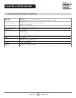
Page 4: ... max IEEE 802 3at 30 watts max IEEE 802 3bt 60 watts max PoE Supported Modes IEEE Alternate A Alt A and 4 Pair Regulatory Compliances UL CE FCC Class A RoHS WEEE REACH Frame Size Up to 10 240 bytes DC Power Requirements 44 to 57 VDC 1 16 A at 56 VDC 3 pin terminal isolated Dimensions 1 0 H x 4 5 W x 6 0 D 2 5 x 11 4 x 15 2 cm Weight 1 1 lb 0 5 kg Operating Temperature Industrial 40 to 167 F 40 to ...

Page 5: ...that provides DC power over twisted pair cable is called Power Sourcing Equipment PSE Equipment that is powered over twisted pair cable is called a Powered Device PD The LGC5600A and LGC5700A are PSE equipment supporting IEEE 802 3af PoE IEEE 802 3at PoE and IEEE 802 3bt PoE 60 W on the RJ 45 port MEDIA CONVERTER DESCRIPTIONS Model Number Description LGC5600A Gigabit Media Converter with 1 SFP and...

Page 6: ...emperature 1310 nm Multimode Fiber 2 km LC 2 km LFP413 SFP 1 25 Gbps Extreme Temperature 1310 nm Singlemode Fiber 10 km LC 10 km LFP414 SFP 1 25 Gbps Extreme Temperature 1310 nm Singlemode Fiber 40 km LC 40 km LFP420 SFP 1 25 Gbps Extreme Temperature 1550 1310 nm Singlemode Simplex Fiber 10 km LC 10 km LFP421 SFP 1 25 Gbps Extreme Temperature 1310 1550 nm Singlemode Simplex Fiber 10 km LC 10 km LF...

Page 7: ...ides a description of each DIP switch position and function DIP SWITCH DEFINITIONS Switch DOWN UP Function 1 Auto 100 SFP Port Fiber Speed 2 N A N A N A 3 AN MAN RJ 45 Port Auto Manual 4 100 10 RJ 45 Port Speed Only in MAN mode 5 FDX HDX RJ 45 Port Duplex Only in MAN mode 6 Off On Pause Capability 7 On Off RJ 45 Port PSE Power 8 N A N A N A 9 Norm Force RJ 45 Port PSE Power Override 10 N A N A N A...

Page 8: ...o auto negotiation with the following modes advertised 1000FDX 1000HDX 100FDX 100HDX 10FDX 10HDX MAN UP 100 DOWN FDX DOWN The RJ 45 port is set to manual negotiation and is forced to 100FDX MAN UP 100 DOWN HDX UP The RJ 45 port is set to manual negotiation and is forced to 100HDX MAN UP 10 UP FDX DOWN The RJ 45 port is set to manual negotiation and is forced to 10FDX MAN UP 10 UP HDX UP The RJ 45 ...

Page 9: ... propagated based on the port notation Port 1 fiber to Port 2 RJ 45 notation indicates the direction the loss of link signal will propagate A loss of receive link on the Fiber Port 1 causes the RJ 45 Port 2 to drop its link due to the propagated state Port 1 to Port 2 The loss of link on the RJ 45 Port 2 does not cause the loss of link to propagate The loss only propagates in the Port 1 to Port 2 ...

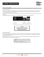
Page 10: ...ocation of the grounding screw REAR VIEW OF THE LGC5600A WITH AC POWER CONNECTOR NEVER ATTEMPT TO OPEN THE CHASSIS OR SERVICE THE POWER SUPPLY OPENING THE CHASSIS MAY CAUSE SERIOUS INJURY OR DEATH THERE ARE NO USER REPLACEABLE OR SERVICEABLE PARTS IN THIS UNIT WARNING DC Power for LGC5700A A power source should be available within 5 ft 1 5 m of the module The over current protection for connection...

Page 11: ...h the circuit breaker to the OFF position Prepare a power cable using a three conductor insulated wire not supplied with 12 AWG to 14 AWG thickness Cut the power cable to the length required Strip approximately 3 8 of an inch of insulation from the power cable wires Connect the power cables to the terminal by fastening the stripped ends to the DC power connector WARNING Note the wire colors used i...

Page 12: ...h at the other end and the RX wavelength must match the TX wavelength at the other end c Connect the Ethernet 10 100 1000 RJ 45 port via a Category 5 or better cable to an external 10BASE T 100BASE TX or 1000BASE T Ethernet PD device STEP 4 VERIFY OPERATION Once the module has been installed and configured per steps 1 through 4 verify the module is operational by viewing the LED indicators The Pow...

Page 13: ...n redundant standby mode Stat OFF Transceiver does not support digital diagnostics or no transceiver SFP is installed Green ON Transceiver SFP supports digital diagnostics and no alarm is detected Amber ON Transceiver SFP supports digital diagnostics and alarms are present RJ 45 PORT INDICATORS Legend Indicator Description 100 OFF No link Green ON Port linked at 100 Mbps Green Blinking at 10 Hz Po...

Page 14: ...when the equipment is operated in a commercial environment Operation of this equipment in a residential area is likely to cause interference in which case the user at his own expense will be required to take whatever measures may be necessary to correct the interference Changes or modifications not expressly approved by the party responsible for compliance could void the user s authority to operat...

Page 15: ...etes que impidan el flujo de aire por los orificios de ventilación 10 El equipo eléctrico deber ser situado fuera del alcance de fuentes de calor como radiadores registros de calor estufas u otros aparatos incluyendo amplificadores que producen calor 11 El aparato eléctrico deberá ser connectado a una fuente de poder sólo del tipo descrito en el instructivo de operación o como se indique en el apa...

Page 16: ...ve consequential or cost of cover damages resulting from any errors in the product information or specifications set forth in this document and Black Box Corporation may revise this document at any time without notice B 2 TRADEMARKS USED IN THIS MANUAL Black Box and the Black Box logo type and mark are registered trademarks of Black Box Corporation Any other trademarks mentioned in this manual are...

Page 17: ...17 1 877 877 2269 BLACKBOX COM NEED HELP LEAVE THE TECH TO US LIVE 24 7 TECHNICAL SUPPORT 1 877 877 2269 NOTES ...

Page 18: ...18 1 877 877 2269 BLACKBOX COM NEED HELP LEAVE THE TECH TO US LIVE 24 7 TECHNICAL SUPPORT 1 877 877 2269 NOTES ...

Page 19: ...19 1 877 877 2269 BLACKBOX COM NEED HELP LEAVE THE TECH TO US LIVE 24 7 TECHNICAL SUPPORT 1 877 877 2269 NOTES ...

Page 20: ...NEED HELP LEAVE THE TECH TO US LIVE 24 7 TECHNICAL SUPPORT 1 877 877 2269 COPYRIGHT 2021 BLACK BOX CORPORATION ALL RIGHTS RESERVED LGC5600A_LGC5700A_USER_REV1 PDF ...

Reviews: