7
CHAPTER 3: Configuration
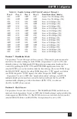
Table 3-2. Possible Settings of DIP Switch Positions 2 Through 5
Pos. 2
Pos. 3
Pos. 4
Pos. 5
Data Rate (Sync. Mode)
ON
OFF
OFF
ON
Async 0 to 19.2 Kbps (2X)
ON
OFF
OFF
OFF
Async 0 to 38.4 Kbps (1X)
ON
ON
ON
OFF
Sync at 2.4 Kbps (1X)
OFF
ON
ON
OFF
Sync at 9.6 Kbps (1X)
OFF
ON
ON
ON
Sync at 9.6 Kbps (2X)
ON
ON
OFF
OFF
Sync at 19.2 Kbps (1X)
ON
ON
OFF
ON
Sync at 19.2 Kbps (2X)
OFF
ON
OFF
OFF
Sync at 38.4 Kbps (1X)
OFF
ON
OFF
ON
Sync at 38.4 Kbps (2X)
ON
OFF
ON
OFF
Sync at 48 Kbps (1X)
ON
OFF
ON
ON
Sync at 48 Kbps (2X)
OFF
OFF
ON
OFF
Sync at 56 Kbps (1X)
OFF
OFF
OFF
OFF
Sync at 64 Kbps (1X)
OFF
OFF
OFF
ON
Sync at 64 Kbps (2X)
OFF
OFF
ON
ON
Sync at 192 Kbps (1X)
ON
ON
ON
ON
Sync at 256 Kbps (1X)
Position 7: Handshake Mode
Use position 7 to set the type of flow control. (This switch position must be
moved to the same setting on both FOMs.) If position 7 is set to ON (the
default setting), the Multimode FOMs perform transparent hardware flow
control by passing the RTS/CTS and DTR/DSR signal pairs from the
attached DTEs across the modem link. In this setting, when one FOM drops
the RS-232 “RTS” signal, the other FOM drops the “CTS” signal, and when
one FOM drops the “DTR” signal, the other drops the “DSR” signal.
If position 7 is set to OFF (the “standard modem” setting), each FOM
independently performs flow control between itself and the local DTE,
automatically adapting to either hardware (RTS/CTS) or software
(X-ON/ X-OFF) flow control.
Position 8: Clock Source
Use position 8 to set the clock source. The MultiMode FOM works from an
internal clock if position 8 is set to OFF (the default setting) and provides this
clock signal on RS-232 Pin 15. The FOM receives an external clock from the
attached RS-232 device on RS-232 Pin 24 if position 8 is set to ON.


