
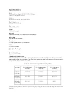

Example Power Budget and Distance Calculations
Power Budget = Transmitter Output - Receiver Sensitivity
Distance = Power Budget ÷ Loss/km
Example:
Receiver Sensitivity = -25.2 dBm
Transmitter Output = -13.4 dBm
Fiber cable Loss/km = 3.5 dB/km
Power Budget = 11.8 dB
Distance = 3.4 km
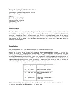
Introduction
The Fiber Driver converts standard RS-232 signals into fiber optic signals, which can then be transmitted over
several kilometers depending on cable type and power setting. These devices support asynchronous, bi-directional
RS-232 data transmission. They are switch selectable for either DTE or DCE applications, eliminating the need for
special cables and preventing confusion during installation. They can be ordered with male or female DB25
connectors for the RS-232 interface. Two units are connected using 50, 62.5, or 100 micron multi-mode fiber optic
cable with ST style connectors.
Installation
Before you begin, make sure all equipment is powered off, including the Fiber Drivers.
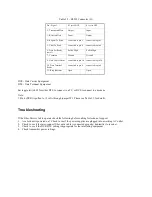
Remove the two screws and lift off the cover to access the internal configuration jumpers on the Fiber Driver. Set
jumpers W1, W2, and W3 as appropriate for your application (see Figure 3.1 and Table 3.1). Reinstall the cover, and
then set toggle switch S1 for either DTE to connect to a PC, or DCE to connect to a modem. Connect the two fiber
drivers using multi-mode fiber optic cables with ST style connectors. Make certain that the transmitter output of
each unit is connected to the receiver input of the other unit. Next, connect the Fiber Drivers to your RS232 devices,
either by attaching the Fiber Drivers directly to the RS232 connector on your devices, or using straight through
cables. Power up the Fiber Drivers, and then apply power to your equipment.
Jumper
Function
Use
W1
Pull-up to +5
Install to assert pin 6 on DB25
W2
High speed filter Install to operate at rates above
19.2 kbps
W3
Range select*
A-short range, B-medium range,
C-long range
*Range selection is dependent upon the core size of the fiber optic cable used and the distance data is to be
transmitted. Select the shortest range that accurately passes data.


