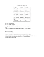
Table 3.2 - RS232 Connector (J1)
Pin - Signal
S1 set to DCE
S1 set to DTE
2 - Transmitted Data
Output
Input
3 - Received Data
Input
Output
4 - Request To Send
connected to pin 5
connected to pin 5
5 - Clear To Send
connected to pin 4
connected to pin 4
6 - Data Set Ready
(note 1)
Pulled High
Pulled High
7 - Common
Ground
Ground
8 - Data Carrier Detect
connected to pin 20
connected to pin 20
20 - Data Terminal
Ready
connected to pin 8
connected to pin 8
22 - Ring Indicator
Open
Open
DCE - Data Carrier Equipment
DTE - Data Terminal Equipment
Set toggle switch S1 for either DTE to connect to a PC, or DCE to connect to a modem.
Note:
1. Pin 6 (DSR) is pulled to +5 volts through jumper W1. Please see Table 3.1 for details.
Troubleshooting
If the Fiber Drivers fail to operate check the following before calling for technical support.
1. Are both units powered on? Check to see if the power supplies are plugged into a working AC outlet.
2. Check to see if the inter-connect fiber optic cable is connected properly; transmitter to receiver.
3. Check to see if the DCE/DTE setting is appropriate for the interfacing equipment.
4. Check transmitter power settings.


