19
APPENDIX: Block Diagram
Appendix: Block Diagram
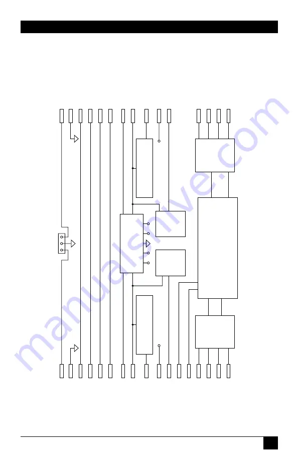
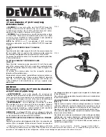
The figure below is a vastly simplified block diagram showing the general
layout of the V.35 Synchronous Modem Eliminator’s circuitry.
DCDA
DCDB
DSRA
DSRB
CTSA
CTSB
RTSA
RTSB
DTRA
DTRB
RDA-
TDB-
RDA+
TDB+
TDA-
RDB-
TDA+
RDB+
SGND
SGND
PGND
PGND
XTC+
XTC-
TCA+
TCB+
TCA-
TCB-
RCA+
RCB+
RCA-
RCB-
S
S
S
1 2 3
S
+V -V
+5V
-5V
RTS/CTS DELA
Y
SELECT
CLOCK SOURCE MODULE
+5V
+5V
POWER SUPPL
Y
CARRIER
CONTROL
SELECT
B
RTS/CTS DELA
Y
SELECT
CARRIER
CONTROL
SELECT
A
LEVEL
CONVERTERS
LEVEL
CONVERTERS
P
O
R
T
A
P
O
R
T
B


