MULTISERVER 500
66
Enhanced FXO Interface Module
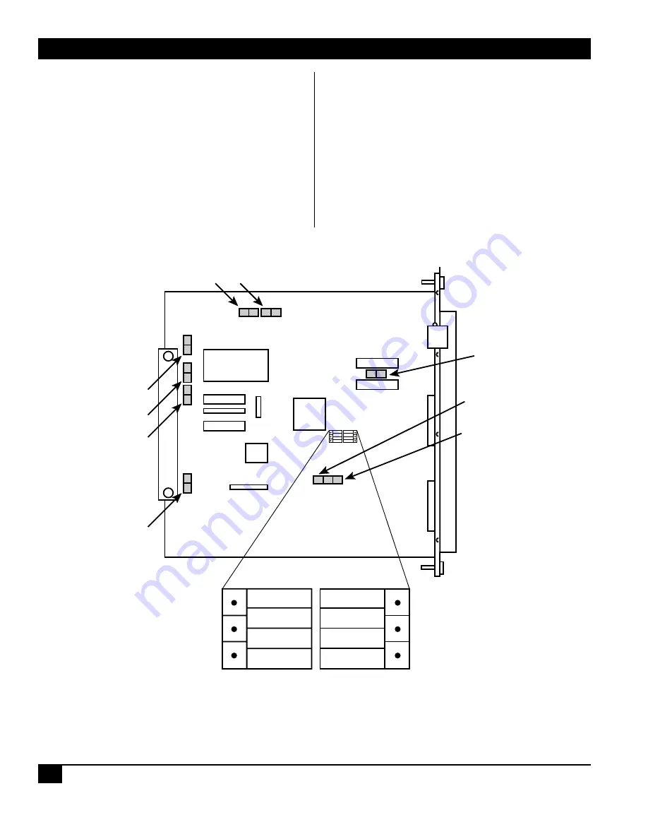
There are 12 movable straps located on the
enhanced FXO interface module: E1 through E5
and E7 through E13 (see Figure B-5). Their
functions are as follows:
1. E1 through E5. These straps are reserved for
internal use and are preset at the factory to
match the type of memory installed. You must
not alter them.
2. Dial Pulse Shaping. Dial pulse shaping is
implemented by an RC network connected
across the dial pulse relay U9. To disconnect
the RC network, remove strap E7.
3. Dial Pulse Series Resistance. This option selects
one of two values of the series resistance in the
dial pulse circuit: 150
Ω
or 50
Ω
(nominal).
The default value is 50
Ω
. To select the 150-
Ω
value, move the strap from E9 to E8.
4. Line Impedance Selection. This option selects
one of two line-impedance values: 600-
Ω
resistive and 600-
Ω
in series with a 2.15-µf
E10
E11
E12
600+2.15
µ
f
(Default)
600
Strapping
Block
E7
E3
E4
E5
E2
E1
E13
E8
E9
T1
U2
K1
Figure B-5. Locations of the Straps on the FXO Interface Module.


