52
MULTI-HEAD SERVSWITCH™
A.3 Cabling Attached to the OPTIONS Port
The DB15 connector labeled “OPTIONS” on the back of the Multi-Head
ServSwitch is a proprietarily pinned port using RS-232-type signaling. You can
connect any of these devices to it:
• The Switch’s optional Remote-Control Module (RCM, see Section 5.2);
• An RS-232 device for serially controlled channel switching (see Section 5.9);
• Another Switch, to create a synchronized system for CPUs with as many as
eight video outputs (see Section 3.3.2); or
• A PC, in order to upgrade the Switch’s firmware (see Section 5.11).
The pinout of this connector is pretty simple: Pin 9 (Signal Ground, SGND),
Pin 10 (Transmit Data, TD), and Pin 11 (Receive Data, RD) are the only pins used
for serial communication to PCs, other Switches, and RS-232 devices. All other pins
are intended for RCM communication only and should be left unconnected;
attaching them to any other RS-232 equipment could have unpredictable and
possibly damaging effects.
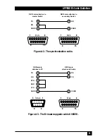
The pinout for a synchronization cable is shown in Figure A-2 on the next page.
We can offer this cable as a special quote, but it’s not a stock item at the time of
this writing. The pinout for a firmware-upgrade cable (product code KV6SER) is
shown in Figure A-3.


