11
CHAPTER 2: Introduction
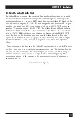
2.2 How the Caller ID Units Work
The Caller ID units receive calls on any of their modular phone-line ports, which
you’ll connect directly to the incoming central-office telephone lines in parallel
with the telephone, key system, or PBX. After detecting the Caller ID data from the
local telephone company, the Caller ID unit stamps this information with the port
number, converts it into ASCII, and transmits it from its RS-232 OUT port to an
attached PC, printer, or other RS-232 DTE. (The Caller ID unit will only indicate
that data has been received if a DTE is connected to the RS-232 OUT port. It will
light its “DATA” LED to indicate that it’s sending data through its RS-232 OUT
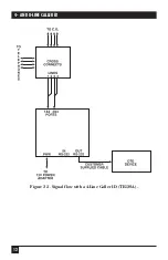
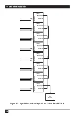
port.) The flow of the data in systems with a single Caller ID unit is shown in
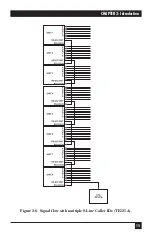
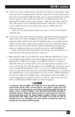
Figures 2-3 and 2-4 on the next two pages; the data flow in systems with multiple
daisychained Caller ID units is shown in Figures 2-5 and 2-6 on the pages that
follow.
What happens to the data after the Caller ID unit transmits it to the DTE is up to
you. You could buy or write a software program to process it (this is often done in
conjunction with a database). But any serial printer, terminal, or PC running a
terminal emulator should be able to accept the data without requiring extra
hardware or software if all you need to do is monitor the data as it’s printed or
appears on screen.
(text continues on page 16)
Summary of Contents for TE120A
Page 13: ...12 4 AND 8 LINE CALLER ID Figure 2 3 Signal flow with a 4 Line Caller ID TE120A ...
Page 14: ...13 CHAPTER 2 Introduction Figure 2 4 Signal flow with an 8 Line Caller ID TE121A ...
Page 15: ...14 4 AND 8 LINE CALLER ID Figure 2 5 Signal flow with multiple 4 Line Caller IDs TE120A ...
Page 16: ...15 CHAPTER 2 Introduction Figure 2 6 Signal flow with multiple 8 Line Caller IDs TE121A ...
Page 29: ...NOTES ...


