16
4- AND 8-LINE CALLER ID
(text continued from page 11)
2.3 Connectors and Pinouts
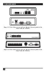
There are several connectors on the Caller ID units. Each 4-Line unit (TE120A)
has two dual-line RJ-14C female telephone-line ports and a barrel-type power inlet.
Each 8-Line unit has eight single-line RJ-11C female telephone-line ports and a
5-pin DIN female power inlet. The RJ-14C and RJ-11C pinouts look like this:
Pin
RJ-14C (TE120A) Signal
RJ-11C (TE121A) Signal
1, 6 [No connection]
[No connection]
2
2nd line (2 or 4) tip
[No connection]
3
1st line (1 or 3) tip
Tip
4
1st line (1 or 3) ring
Ring
5
2nd line (2 or 4) ring
[No connection]
Both 4- and 8-Line units have two RS-232 ports whose data rate, parity, data bits,
and flow control are all user-selectable (see
Section 3.2
). The RS-232 OUT port is a
DB9 female connector pinned as an RS-232 DCE port. (This means that it actually
transmits
data on its Receive Data lead, as a modem would.) It’s designed to be
connected to printers, terminals, PCs running terminal emulators, and other
DTEs. (In daisychained applications, it can be connected to the RS-232 IN port of
the next Caller ID unit in the chain.) The RS-232 OUT port is pinned this way:
Pin
Signal
Direction
1
Carrier Detect (CD)
Out (to other device)
2
Receive Data (RD)
Out (to other device)
5
Signal Ground (SGND)
N/A
6
Data Set Ready (DSR)
Out (to other device)
7
Request to Send (RTS)
In (from other device)
8
Clear to Send (CTS)
Out (to other device)
9
Busy
Out (to other Caller ID unit)
NOTES
Pin 7, RTS, must be pulled active (high) in order for the Caller ID unit to
turn on its DATA LED when it receives Caller ID information from a
telephone line.
Pin 9, Busy, is a proprietary signal used primarily for communication
between daisychained Caller ID units, although it can be connected to
Pin 22, Ring Indicator (RI), on a DTE with a DB25 serial port, as shown in
Table 4-1 at the end of
Chapter 4
.
Summary of Contents for TE120A
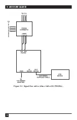
Page 13: ...12 4 AND 8 LINE CALLER ID Figure 2 3 Signal flow with a 4 Line Caller ID TE120A ...
Page 14: ...13 CHAPTER 2 Introduction Figure 2 4 Signal flow with an 8 Line Caller ID TE121A ...
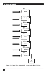
Page 15: ...14 4 AND 8 LINE CALLER ID Figure 2 5 Signal flow with multiple 4 Line Caller IDs TE120A ...
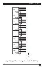
Page 16: ...15 CHAPTER 2 Introduction Figure 2 6 Signal flow with multiple 8 Line Caller IDs TE121A ...
Page 29: ...NOTES ...

