19
CHAPTER 3: Configuration
3.2 DIP Switch S2
DIP switch S2 controls both the unit number (if you’ll be daisychaining Caller ID
units) and the serial communication characteristics of the RS-232 OUT and RS-232
IN ports (see
Section 2.3
) and the unit number (if you will be daisychaining Caller
ID units). (All of the possible settings of S2’s switch positions that aren’t listed
below are invalid—do
not
use unlisted settings, because they could disable or
damage attached equipment.)
Use positions 1 and 2 to set the data rate of the RS-232 OUT port:
•
1 OFF, 2 OFF:
1200 bps.
•
1 ON, 2 OFF:
2400 bps.
•
1 OFF, 2 ON:
4800 bps.
•
1 ON, 2 ON:
9600 bps (factory-default setting).
Use position 3 to set the data bits of the RS-232 OUT port:
•
3 OFF:
7 data bits.
•
3 ON:
8 data bits (factory-default setting).
Use positions 4 and 5 to set the parity of the RS-232 OUT port:
•
4 OFF, 5 OFF:
No parity (factory-default setting).
•
4 ON, 5 OFF:
Odd parity.
•
4 OFF, 5 ON
or
4 ON, 5 ON:
Even parity.
Use positions 6, 7, and 8 to set the unit number: “1” for a single unit or “1,” “2,”
etc., for daisychained units successively
closer to
the DTE. For example, if you have
three 4-Line units in a daisychain, you must set the one
farthest from
the DTE as
unit #1, the one in the middle as unit #2, and the one attached to the DTE as #3.
(However, if you’ll have 4-Line and 8-Line units in the same daisychain, see the
Note at the start of
Chapter 4
.) The possible settings are:
•
6 OFF, 7 OFF, 8 OFF:
Unit is #1 (factory-default setting).
•
6 ON, 7 OFF, 8 OFF:
Unit is #2.
•
6 OFF, 7 ON, 8 OFF:
Unit is #3.
.•
6 ON, 7 ON, 8 OFF:
Unit is #4.
•
6 OFF, 7 OFF, 8 ON:
Unit is #5.
•
6 ON, 7 OFF, 8 ON:
Unit is #6.
•
6 OFF, 7 ON 8 ON:
Unit is #7.
•
6 ON, 7 ON, 8 ON:
Unit is #8
Summary of Contents for TE120A
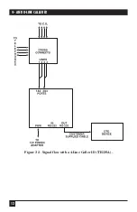
Page 13: ...12 4 AND 8 LINE CALLER ID Figure 2 3 Signal flow with a 4 Line Caller ID TE120A ...
Page 14: ...13 CHAPTER 2 Introduction Figure 2 4 Signal flow with an 8 Line Caller ID TE121A ...
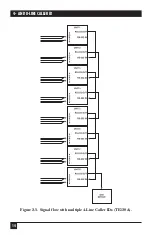
Page 15: ...14 4 AND 8 LINE CALLER ID Figure 2 5 Signal flow with multiple 4 Line Caller IDs TE120A ...
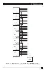
Page 16: ...15 CHAPTER 2 Introduction Figure 2 6 Signal flow with multiple 8 Line Caller IDs TE121A ...
Page 29: ...NOTES ...

