22
4- AND 8-LINE CALLER ID
6.
If you’re daisychaining Caller ID units:
Run a straight-though-pinned (Pin 1 to 1,
2 to 2, etc) DB9 male-to-female cable (not included, product code EDN12H-MF)
from the DB9 male RS-232 IN port of the highest-numbered unit in the chain
(the one attached to the DTE) to the DB9 female RS-232 OUT port of the
next-highest-numbered unit. Repeat this process for each additional unit in
the daisychain, finishing by connecting the last such cable to the RS-232 OUT
of unit #1. If you include only 8-Line units, there can be eight total units in
your daisychain serving up to 64 total lines. If you include any 4-Line units,
you can serve up to 32 total lines; the maximum number of 4-Line units in
your daisychain will be eight minus twice the number of 8-Line units present:
• No 8-Line units = eight 4-Line units.
• One 8-Line unit = six 4-Line units.
• Two 8-Line units = four 4-Line units.
• Three 8-Line units = two 4-Line units.
• If you use four or more 8-Line units, you can’t include any 4-Line units.
7. Attach the output cord of each Caller ID unit’s power supply to the Power
connector on the back of the unit.
8. Plug each power supply’s input cord into a working AC outlet. The
corresponding Caller ID unit should power up immediately (it has no
ON/OFF switch) and light its Power LED.
9. Plug in and boot up the DTE device attached to the (first) Caller ID unit. If
the DTE is a PC, run its terminal-emulator program. Make sure the DTE or
the terminal-emulator program are set to receive RS-232 data using the same
data rate and data format that the Caller ID unit is set for (see
Section 3.2
).
Your Caller ID system should now be ready for continuous operation.
Table 4-1. Pinning of a DB9 to DB25 serial cable.
DB9M attaches
DB25F attaches
to Caller ID’s
to DTE’s
RS-232 OUT port:
serial port:
Signal
Pin
Pin
Signal
CD
1 ..................8
CD
RD
2 ..................3
RD
SGND
5 ..................7
SGND
DSR
6 ..................6
DSR
RTS
7 ..................20
DTR
CTS
8 ..................5
CTS
BUSY
9 ..................22
RI
>
>
>
<
>
>
Summary of Contents for TE120A
Page 13: ...12 4 AND 8 LINE CALLER ID Figure 2 3 Signal flow with a 4 Line Caller ID TE120A ...
Page 14: ...13 CHAPTER 2 Introduction Figure 2 4 Signal flow with an 8 Line Caller ID TE121A ...
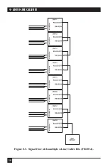
Page 15: ...14 4 AND 8 LINE CALLER ID Figure 2 5 Signal flow with multiple 4 Line Caller IDs TE120A ...
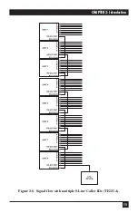
Page 16: ...15 CHAPTER 2 Introduction Figure 2 6 Signal flow with multiple 8 Line Caller IDs TE121A ...
Page 29: ...NOTES ...

