background image

Page 4

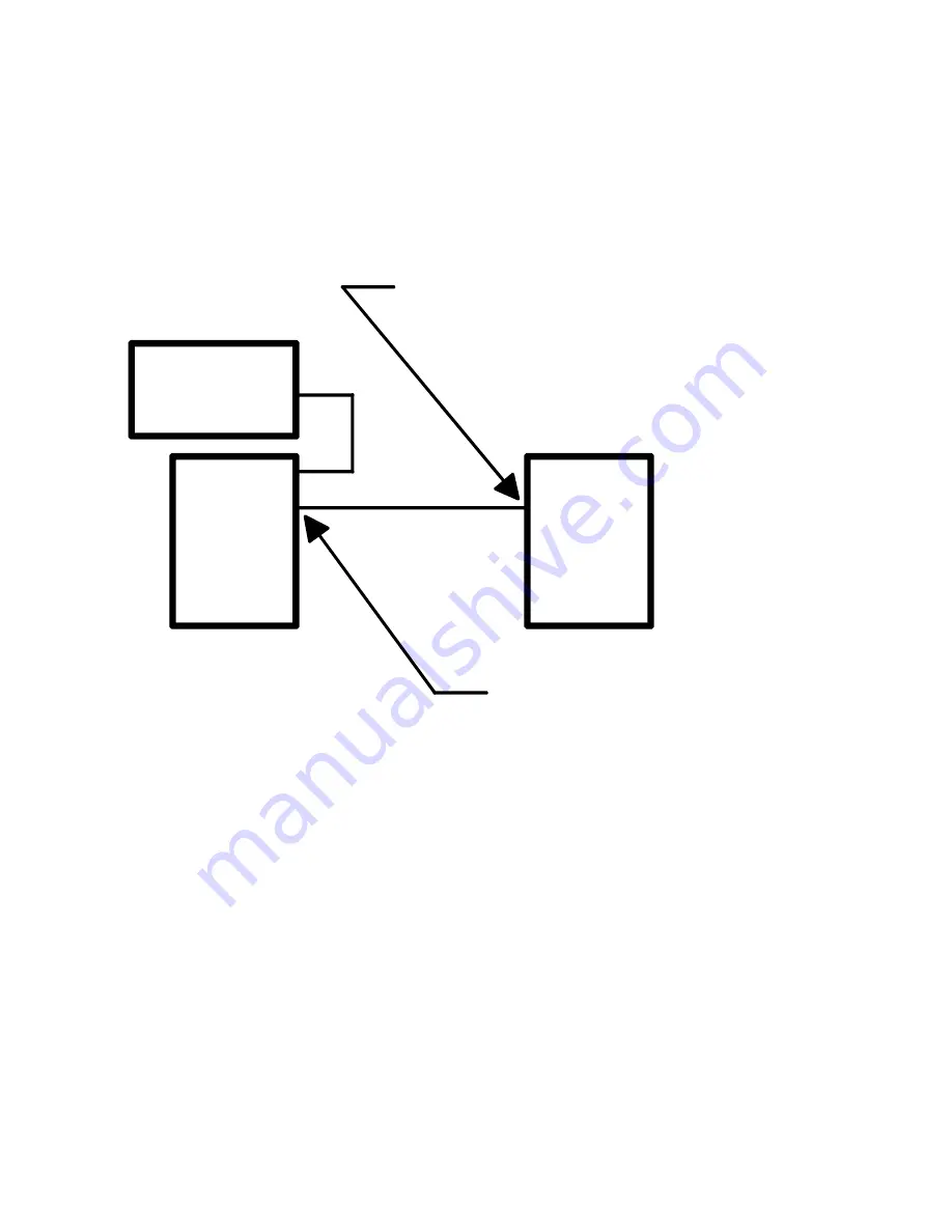
V.11 LS

MODEM

CONNECT TO "INPUT" PORT

CONNECT TO "OUTPUT" PORT

DB-15 CABLE

OR F.E.P.

V.11 LS

3.4

EQUIPMENT GROUNDING

Jumper 

JMP1

 provides for grounding interconnection in those systems requiring a connec-

tion between Pin #1 (

frame ground

) and Pin # 8 (

signal ground

). Please reference Appendix

B for further strapping details.

Figure  3-2
Cascading Diagram

Summary of Contents for TL576A

Page 1: ...eek Phone orders 24 hours 7 A M Monday to midnight Friday Saturday 8 to 4 Eastern Mail order Black Box Corporation 1000 Park Drive Lawrence PA15055 1018 Web site http www blackbox com E mail info blackbox com CUSTOMER SUPPORT INFORMATION NOVEMBER 1998 MODEL TL576A POWER DATA CLOCK INDICATE V 11 LS V 11 LS V 11 Data Broadcast Unit ...

Page 2: ...nt is operated in a commercial environment Operation of this equipment in a residential area is likely to cause interference in which case the user at his own expense will be required to take whatever measures may be necessary to correct the interference Changes or modifications not expressly approved by the party responsible for compliance could void the user s authority to operate the equipment ...

Page 3: ...ferido a personal de servicio calificado 9 El aparato eléctrico debe ser situado de tal manera que su posición no interfiera su uso La colocación del aparato eléctrico sobre una cama sofá alfombra o superficie similar puede bloquea la ventilación no se debe colocar en libreros o gabinetes que impidan el flujo de aire por los orificios de ventilación 10 El equipo eléctrico deber ser situado fuera d...

Page 4: ...do expuesto a la lluvia o D El aparato parece no operar normalmente o muestra un cambio en su desempeño o E El aparato ha sido tirado o su cubierta ha sido dañada 17 Cuidado debe ser tomado de tal manera que objectos liquidos no sean derramados sobre la cubierta u orificios de ventilación 16 El cable de corriente deberá ser desconectado del cuando el equipo no sea usado por un largo periodo de tie...

Page 5: ...PERATION 2 2 1 OPERATION 2 2 2 X 21 PORT PINOUTS 2 2 3 FRONT PANEL LED INDICATORS 2 CHAPTER 3 SETUP AND INSTALLATION 3 3 1 POWER CONNECTION 3 3 2 INSTALLATION 3 i 3 4 EQUIPMENT GROUNDING 3 APPENDIX A ADDRESSES OF STANDARDS ORGANIZATIONS 5 APPENDIX B TECHNICAL INFORMATION 6 5 1 STRAPPING INFORMATION 6 5 2 TECHNICAL SPECIFICATIONS 7 ...

Page 6: ...d control signal from the main input data source may be used The input signals are split with the internal circuitry and rebroadcast on the eight output ports The V 11 LS is housed in a sturdy aluminum enclosure and is supplied with an internal linear power supply The unit has a 110 220 VAC rotary select switch located on the rear of the housing The unit can operate on standard AC power found in a...

Page 7: ... are four green LEDs The Power indicator marked POWER illuminates when AC voltage is applied to the box Three adjacent LED i ndi cat or si l l um i nat ei nconj unct i on wi t h Receive Data DATA Receive Clock CLOCK and the user defined control signal which is marked INDICATE The DATA and CLOCK LEDs will flash on and off at a constant rate regardless of the user s clock and data rate The INDICATE ...

Page 8: ...V 11 X 21 compliant devices into the sub channels ports on the back of the V 11 LS 3 3 CASCADING AND TERMINATION RESISTORS If more than one V 11 LS are to receive Data Clock and Indicate from the same source a shielded DB 15 one to one extension cable with a male DB 15 on one end and a female DB 15 on the other end can be used to link the V 11 LS together The box furthest from the source of the da...

Page 9: ...ABLE OR F E P V 11 LS 3 4 EQUIPMENT GROUNDING Jumper JMP1 provides for grounding interconnection in those systems requiring a connec tion between Pin 1 frame ground and Pin 8 signal ground Please reference Appendix B for further strapping details Figure 3 2 Cascading Diagram ...

Page 10: ...00 AT T Bell Publications documents may be reached by calling 800 344 0223 or 800 432 6600 ANSI American National Standards Institute 1430 Broadway New York NY 10018 Telephone 212 354 3300 EIA Electronic Industries Association 2001 Eye Street N W Washington DC 20006 Telephone 202 457 4966 FED STD General Services Administration Specification Distribution Branch Building 197 Washington Navy Yard Wa...

Page 11: ...Hold this space for the strapping chart Page 6 APPENDIX B STRAPPING INFORMATION ...

Page 12: ...1 Female Male DB 15 connectors Enclosure Metal Aluminum Approvals UL 1950 FCC Class A CE EN60950 CE EN55022 CE EN50082 1 Front Panel Indicators Power Data Clock and Indicate Power Requirement 100 120 200 220 VAC 10 47 to 63 Hz 5 Watts Switch selectable Environmental Operating Temperature 32º to 122º F 0º to 50º C Relative Humidity 5 to 90 Non Condensing Altitude Up to 10 000 feet 3048 meters Dimen...

Page 13: ......

Page 14: ...i i C i 1000 Park Drive Lawrence PA 15055 1018 724 746 5500 Fax 724 746 0746 Copyright 1998 Black Box Corporation All rights reserved ...

Reviews: