background image

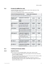
Port pairs

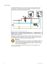
The port pairs of valve lines A and B have A1/B1 and A2/B2 marks.
Always connect each motor to a port pair as shown in the figure below.

Figure 6. The port pairs.

You can connect left and right side motors to one of the two port pairs.

4.5

System design

Product manual

17

Summary of Contents for CTR101

Page 1: ...Product manual On Demand Drive System CTR101 CTR201 and CVM120 CVU200 valves ...

Page 2: ...3 4 4 Hydraulic connections 14 4 5 Port pairs 17 5 Control system 18 5 1 Model series of the control system 18 5 2 Product identification code 19 5 3 Control system connections 19 5 3 1 Important notes 19 5 3 2 Control system connection diagrams 20 5 3 3 Display cable with extension 22 5 3 4 Pressure sensor cables 22 5 3 5 Brake signal cable 23 5 3 6 Valve cable Y 23 5 3 7 Valve cable straight 23 ...

Page 3: ...bleeding procedure 31 6 4 Examine the connections 32 6 5 Test drive 32 7 Technical data 34 7 1 Control device 34 7 2 Display 35 7 3 Display mount 36 7 4 Pressure sensor 37 7 5 CVM120 2WD valve 38 7 6 CVM120 2WD HDC valve 39 7 7 CVM120 4WD valve 40 7 8 CVM120 4WD HDC valve 41 7 9 CVU200 valve 42 Contents Product manual 3 ...

Page 4: ...20 CVU200 valves and the CTR101 CTR201 control systems are part of the Black Bruin On Demand Drive System Black Bruin On Demand Drive System is a transmission solution for tractor driven trailers and working equipment Black Bruin On Demand Drive System is very applicable for equipment that periodically requires additional power and is towed without hydraulics Black Bruin On Demand Drive System is ...

Page 5: ...ntification The valves and the control systems have identification plates Refer to the CTR101 or CTR201 Operation manual for the instructions on how to verify the software version of the control system Figure 1 Identification plate of the valve 1 Part number 2 Model 3 Serial number 4 Manufacturing date 5 Reference number 6 Maximum allowed operating pressure Figure 2 Identification plate of the con...

Page 6: ...ent and attachments when you lift and move the product Make sure that it is not possible to pressurize the hydraulic lines during product installation and maintenance procedures During the operation the product temperature can be over 60 ºC 140 F Hot surfaces can burn you Be careful of hot hydraulic fluid when you disconnect the hydraulic connections Warning symbols The following symbols are used ...

Page 7: ... extensive driving speed range with inbuilt two speed valve 3 Control device Controls the system functions Controls the valve Measures the pressure from the system s pressure sensors Monitors the brake signal Monitors the external alarm signal optional Controls the application specific auxiliary valve optional Stores the system settings Collects the speed and direction information via tractor s IS...

Page 8: ...use hydraulic motors in the operating modes that follow Driving mode Driving mode with HDC function Hill descent control option Freewheeling mode The chapters that follow give the working principles of these modes Driving mode In this mode the motors help the vehicle to move in the direction of travel You can adjust the tractive power level to the driving conditions The power level stays constant ...

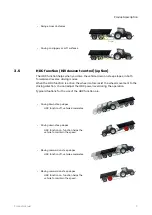
Page 9: ... the driving direction You can adjust the HDC power level during the operation Typical situations for the use of the HDC function are Driving down steep slopes HDC function off vehicle accelerates Driving down steep slopes HDC function on function helps the vehicle to maintain the speed Moving rearward on steep slopes HDC function off vehicle accelerates Moving rearward on steep slopes HDC functio...

Page 10: ...rking range If the pressure level is not sufficient due to increased driving speed the control system automatically switches to freewheeling This protects the motor from overloading The operator can also manually change the mode to freewheeling Typical situations to operate in the freewheeling mode are When you drive on road When you do work above the maximum working speed range When the working c...

Page 11: ...en the drive is in use The available flow from the pump and the flow capacity of the selected valve gives the maximum flow of the system The 2 speed motor option makes it possible to use the partial displacement of the motor Thus you can use the drive in higher speed Guidelines to select the motors for the On Demand Drive System Necessary Mechanical freewheeling Recommended 2 speed function Possib...

Page 12: ...es have the in built functions that follow Mode change between the freewheeling and driving modes Drive direction control Motor 2 speed function control Flow limitation for Assisting traction control ATC Proportional pressure level control Proportional Hill descent control HDC available in selected valve models When a wheel slips the ATC function gives up to 50 of the maximum flow of the valve to ...

Page 13: ... Hill descent control HDC option If the cooling is not sufficient the hydraulic fluid temperature can raise during the continuous use of the HDC function at high pressure The conditions that have an effect on the necessary cooling capacity are for example The working pressure The flow The ambient temperature The duty cycle Note The working pressure line P of the system must have a pressure relief ...

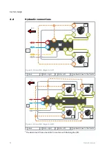
Page 14: ...ight 3 Motor left 4 Hydraulic lines to the tractor Y LS P C Y A A A B B B T C B 2 1 C A 2 3 3 4 A A B B C Y C Y Y Figure 4 Connection diagram 4WD 1 Valve 2 Motor right 3 Motor left 4 Hydraulic lines to the tractor The drain line C has a mark C2 in motors with flushing line C1 4 4 System design 14 Product manual ...

Page 15: ...r valves Note The flow direction is from line P to line T Attention Do not put together lines C and T Always connect the line C to the reservoir without valves Table 2 Port sizes Port Description CVM120 valve CVU200 valve P Pump Working pressure inlet G3 4 G1 T Tank Return line G3 4 G1 C Drain Case leakage G3 4 G1 A1 B1 A2 B2 Working lines for the motors G1 2 G3 4 Y 2 speed function control line G...

Page 16: ... control systems have an AUX output function to control the external valve from the display You can use this to control the selector valve A maximum permitted current for the valve is 4 A 48 W 12 V DC Attention You must connect the pressure inlet port P of the CVM120 CVU200 valve to the de energized position of the selector valve The auxiliary valve output is always de energized during the driving...

Page 17: ...es A and B have A1 B1 and A2 B2 marks Always connect each motor to a port pair as shown in the figure below Figure 6 The port pairs You can connect left and right side motors to one of the two port pairs 4 5 System design Product manual 17 ...

Page 18: ...tching to freewheeling Automatic based on low pressure Automatic based on speed ISOBUS Manual freewheeling Shifting between low and high speed range 2 speed function Manual shift M Automatic shift Assisting traction control modes ATC Automatic mode activation and deactivation based on speed Activated after forward drive activation for a set time Continuous operation 4WD valve control O O HDC valve...

Page 19: ...DDD EE FF CTR101 CTR201 I10 10 m power ISOBUS cable with ISOBUS implement connector and terminating bias circuit P10 10 m power cable with free leads EE Options 1 AAAAAA BB CCC DDD EE FF CTR101 CTR201 H0 default not defined FF Options 2 AAAAAA BB CCC DDD EE FF CTR101 CTR201 C0 default not defined Control system connections Important notes When you plan to use the CTR101 CTR201 control system make ...

Page 20: ...control device again if the display cable disconnects and you connect it when the control system power is on Switch the power off and on again CTR201 Make sure that the tractor obeys the ISOBUS class 2 requirements The automatic drive control mode will not operate correctly with an ISOBUS class 1 tractor CTR201 Always use the ISOBUS implement connector IBBC when you connect the system to the tract...

Page 21: ...ngth m 2 Valve cables WV1 P_A WV3 P_B PDB WV2 1 3 Brake signal cable Brake_sig 10 4 Pressure sensor cables M_A M_B 1 5 Display cable extension Display 10 0 3 6 CTR101 Power cable CTR201 Power ISOBUS cable See chapter Power cable types on page 24 Master Slave 10 7 Controller link 1 8 Resistor plug 9 External alarm signal cable accessory 1 10 HDC AUX valve cable accessory 2 1 1 In CTR201 control sys...

Page 22: ...akes it possible to disconnect the display without removing it from the display carrier Cable type Straight 2 1 Length 0 3 m Head 1 design M12x1 5 pin that connects to the display cable 10 m main cable Head 2 design M12x1 5 pin that connects to the display Pressure sensor cables Use Connects the pressure sensors to the control device Cable type Straight 1 2 Length 1 m Head 1 design Deutsch DT06 6S...

Page 23: ...0 V ground level Valve cable Y Use Connects the control device to valves Cable type Y cable 1 2 Length Each branch 1 m Head 1 design Deutsch DT06 6S connector that connects to the control device Head 2 design 2 x Deutsch DT06 2S connectors that connect to the valves Valve cable straight Use Connects the control device to valves Cable type Straight 1 2 Length 1 m Head 1 design Deutsch DT06 6S conne...

Page 24: ...cable types Power cable for CTR101 Supply kit P10 in the identification code 1 2 L Head 1 design L Length m Head 2 design Free conductors 4 2 and 2 10 AMP MCP2 8F Power ISOBUS cable for CTR201 Supply kit I10 in the identification code 1 2 3 4 5 L2 L1 L3 1 Isobus implement connector 2 Branching tube 3 AMP MCP2 8F 4 Aptiv 1205248 5 Terminating bias circuit L1 10 m L2 0 5 m L3 0 5 m 5 3 8 5 3 9 Contr...

Page 25: ...le to power the two control devices Cable type Y 1 2 Length Each branch 0 5 m Head 1 design AMP MCP E connector to connect to the power cable Head 2 design 2 x AMP MCP2 8F connectors to connect to the two control devices In the CTR201 control system the branches have labels for master and slave control devices see the 4WD connection diagram in chapter Protective caps Use To protect the connectors ...

Page 26: ...alves Head 2 pinouts 1 output 2 ground Extension adapter cable for AUX valve optional accessory Part number 50241004 Use Extends the AUX valve cable and connects to the valve that has the DIN43650 type A connector Note This cable is an extension cable for the HDC AUX valve ca ble that is necessary Cable type Straight 1 2 Length 5 m Head 1 design Deutsch DT04 2P connector that connects to the HDC v...

Page 27: ...eutsch DT06 6S connector that connects to the control device Head 2 design Free conductors to connect to the alarm input circuit Wiring Red supply for circuit 12 V Black signal 0 12 V Brown ground The signal that you connect must be of a binary type on off The con nected signal can be either Normally low 0 V signals Normally high 12 V signals The figure shows an example of a connection of an elect...

Page 28: ...hapter Hydraulic connections on page 14 Note Be very careful with the drain line C connections Make sure that the drain line to the reservoir does not have pressure If you pressurize the drain line the hydraulic motor sealings break Mark the hoses This is very important if the hydraulic supply is in the tractor 6 Install the system s pressure sensors 400 bar to the measurement points M_A2 and M_B2...

Page 29: ...ve CVM120 valve only If the tractor does not have the LS connection plug the LS port on the valve Note Refer to the technical data for the locations of measurement points ports etc see chapter Technical data on page 34 9 Install the control device to an applicable location from the attachment points Danger Make sure that the system power is not on before you install the control device 10 Connect a...

Page 30: ... are not in use protective caps are included in the delivery Power up the control system 1 Power up the control system 2 Make sure that the system configuration is correct 2WD No text on the control device segment display The green PWR led flashes Figure 9 2WD Control device segment display 4WD One of the control devices shows A on the segment display and the other shows B on the segment display T...

Page 31: ... at a time Find the air bleeding screws on the housing Turn the motor to a position in which the screw is at its topmost position You can use the control system to drive the motors to the correct position Note Use the 25 power setting Keep the ATC function activated during the air bleeding procedure Note CTR201 only Use the manual driving mode 4 Loosen the air bleeding screw half a turn 5 Drive th...

Page 32: ...les is correct Do the steps that follow a Disconnect the cable from the pressure sensor on the measuring point M_A2 on the valve b The alarm message Sensor_failure_ pressure_A shows on the display c Connect the cable again d Do the steps a thru c for the pressure sensor on the measuring point M_B2 on the valve The alarm message Sensor_failure_ pressure_B shows on the display 3 Activate the forward...

Page 33: ...e power levels during the drive c The measured value on the display decreases and increases with the level change d If the measured value does stay clearly below the 100 when you use the maximum tractive power level decrease the value of the parameter Maximum pressure level bar Note The measured values can be different from the selected levels This is usual for low tractive power levels 5 Change t...

Page 34: ...evice attachment point dimensions D x E 52 mm x 205 5 mm Protection class IP 65 connectors attached IP 67 Operating temperature 40 85 C Operating voltage 12 V DC Power consumption Max 15 A Note Free space required for connectors and connector cables 100 mm above the control device and 100 mm in front of the power connector 7 7 1 Technical data 34 Product manual ...

Page 35: ...nsions External dimensions A x B x C D 87 5 mm x 87 5 mm x 37 8 mm 31 3 mm Opening size in panel installation 81 5 0 5 mm x 81 5 0 5 mm Protection class IP 67 installed IP 65 not installed Operating temperature 20 70 C 7 2 Technical data Product manual 35 ...

Page 36: ...ial External dimensions 1 Mounting arm Aluminum black anodized A B 128 mm 95 mm 2 Mounting plate Aluminum black anodized Diameter C 62 mm 3 Display carrier Plastic black D E x F 68 mm 62 mm x 93 mm 4 Ball Rubber 7 3 Technical data 36 Product manual ...

Page 37: ...C A Figure 13 Pressure sensor main dimensions External dimensions A x B D 71 5 mm x 21 8 mm 25 4 mm Measurement range 0 400 bar Cable connector Deutsch DT04 3S Process connection C G1 4 7 4 Technical data Product manual 37 ...

Page 38: ... Maximum pressure level 350 bar Maximum flow rate 120 l min Operating voltage 12 V DC Compatible pump Load sensing LS or fixed displacement operation type is selected from the valve Refer to the valve datasheet for more detailed technical information and dimensions M_B M_A P_B PDB WV1 P_A WV3 WV2 DW Figure 15 CVM120 2WD valve locations of the valve connections 7 5 Technical data 38 Product manual ...

Page 39: ...Maximum pressure level 350 bar Maximum flow rate 120 l min Operating voltage 12 V DC Compatible pump Load sensing LS or fixed displacement operation type is selected from the valve Refer to the valve datasheet for more detailed technical information and dimensions M_B M_A P_B PDB WV1 P_A WV3 WV2 DW PDB2 Figure 17 CVM120 2WD HDC valve locations of the valve connections 7 6 Technical data Product ma...

Page 40: ... Maximum pressure level 350 bar Maximum flow rate 120 l min Operating voltage 12 V DC Compatible pump Load sensing LS or fixed displacement operation type is selected from the valve Refer to the valve datasheet for more detailed technical information and dimensions M_B M_A P_B PDB WV1 P_A WV3 WV2 DW Figure 19 CVM120 4WD valve locations of the valve connections 7 7 Technical data 40 Product manual ...

Page 41: ...kg Maximum pressure level 350 bar Maximum flow rate 120 l min Operating voltage 12 V DC Compatible pump Load sensing LS or fixed displacement operation type is selected from the valve Refer to the valve datasheet for more detailed technical information and dimensions M_B M_A P_B PDB WV1 P_A WV3 WV2 DW PDB2 Figure 21 CVM120 4WD HDC valve locations of the valve connections 7 8 Technical data Product...

Page 42: ...m Weight 36 0 KG Maximum pressure level 350 bar Maximum flow rate 200 l min Operating voltage 12 V DC Compatible pump Load sensing LS external LS interface Power Be yond Refer to the valve datasheet for more detailed technical information and dimensions M_B P_B PDB P_A WV3 WV2 WV1 M_A Figure 23 CVU200 locations of the valve connections 7 9 Technical data 42 Product manual ...

Page 43: ...KYLÄ FINLAND www blackbruin com info blackbruin com All the information contained in this publication is based on the latest information available at the time of publication Black Bruin Inc reserves the right to make changes without prior notice EN 26 02 2021 ...

Reviews: