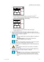
• Attach the control device near the valve and in a location where the mechanical
shocks or wear cannot cause damage to it. If necessary, use mechanical
protection.
• Make sure that the installation location of the cables:
• Does not cause too much force on the cables
• Is not abrasive
• Does not let the cables catch between the moving parts of the machine and
break them.
• The system components are classified as water-resistant, but do not put the
components fully into water.
• Install the display in the tractor cab. Use the mounting set that is supplied with
the display. It includes a mounting frame and a pivot arm.
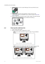
• You must start the control device again if the display cable disconnects and you
connect it when the control system power is on. Switch the power off and on
again.
• CTR201: Make sure that the tractor obeys the ISOBUS class 2 requirements. The
automatic drive control mode will not operate correctly with an ISOBUS class 1
tractor.
• CTR201: Always use the ISOBUS implement connector (IBBC) when you connect
the system to the tractor.
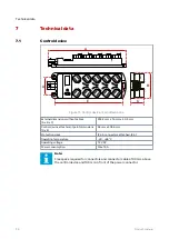
Control system connection diagrams
8
6
4
2
CAN OUT
7
5
3
1
CAN IN
6
3
2
WV1
P_A
WV3
M_B
M_A
PDB
+12V
12 V DC
WV2
2
1 PDB2
P_B
1
4
+12V
5
8
9
7
!
AUX
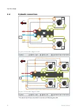
Figure 7. Connection diagram, 2WD.
1
Control device
Cables
Description
Cable ID
Length [m]
2
Valve cables
WV1 / P_A
WV3 / P_B
PDB / WV2
1
3
Brake signal cable
Brake_sig
10
4
Pressure sensor cables
M_A, M_B
1
5
Display cable + extension
Display
10 + 0.3
5.3.2
Control system
20
Product manual


